
Liquid cooling apparatus with automatic heat dissipation function

A heat dissipation device and heat exchange device technology, applied in the direction of cooling/ventilation/heating transformation, electrical components, electrical equipment structural parts, etc., can solve the problems of reducing the temperature of high-power devices, device power consumption, damage, etc., to achieve increased The effect of the cooling process

Active Publication Date: 2018-11-23
常州天力兰宝科技股份有限公司
View PDF5 Cites 3 Cited by
  • Summary
  • Abstract
  • Description
  • Claims
  • Application Information

AI Technical Summary

Problems solved by technology

With the advancement and development of science and technology, some high-power devices are used more and more frequently. Long-term use will increase the overall power consumption and heat generation of the device, causing its temperature to rise continuously. If it is not dissipated in time, these high-power Devices tend to fail or be damaged by high temperature
[0003] Nowadays, the most widely used heat dissipation method is liquid cooling technology, which can use components such as radiators and heat exchangers to realize the circulation of coolant through pipes, so as to reduce the temperature of high-power devices. Most of the devices are not easy to disassemble and replace, and the cooling speed is relatively slow

Method used


Image

  • Liquid cooling apparatus with automatic heat dissipation function
  • Liquid cooling apparatus with automatic heat dissipation function
  • Liquid cooling apparatus with automatic heat dissipation function

Examples


Embodiment Construction

[0041] The following will clearly and completely describe the technical solutions in the embodiments of the present invention with reference to the accompanying drawings in the embodiments of the present invention. Obviously, the described embodiments are only some, not all, embodiments of the present invention. Based on the embodiments of the present invention, all other embodiments obtained by persons of ordinary skill in the art without making creative efforts belong to the protection scope of the present invention.

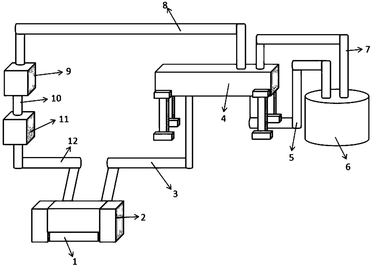
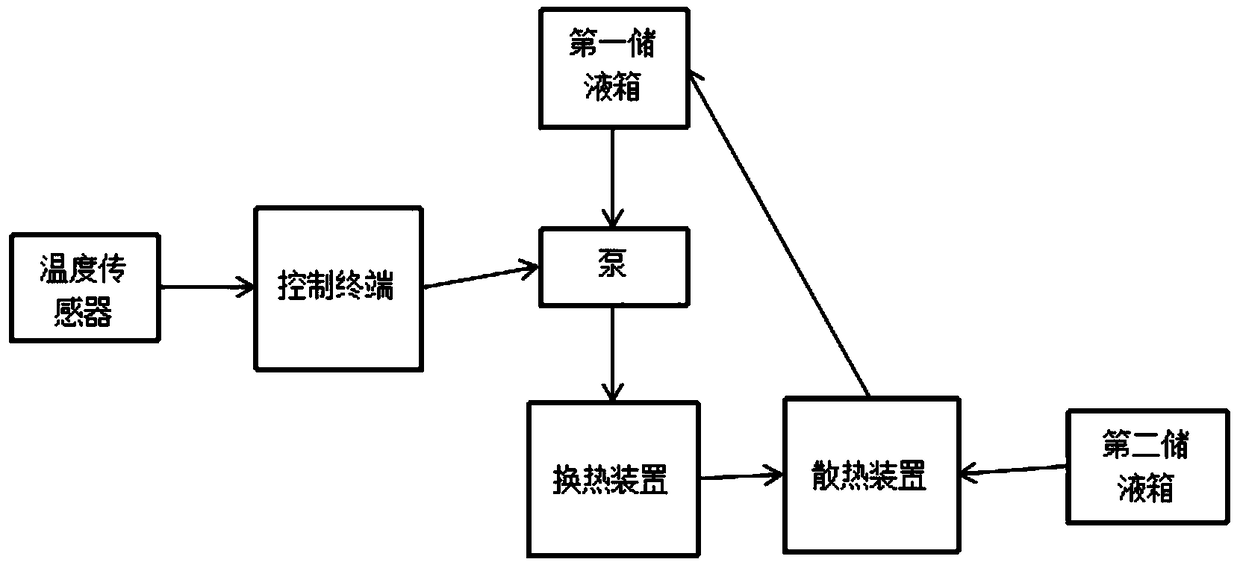
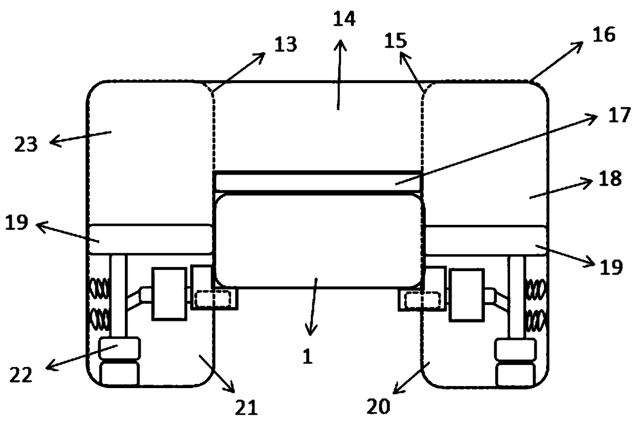
[0042] see Figure 1-13 , in an embodiment of the present invention, an automatic heat dissipation liquid cooling device, the liquid cooling device includes a heat dissipation device 1, a heat exchange device 2 installed on the heat dissipation device 1, a heat dissipation device 4, a pump 11, a first storage The liquid tank 9 and several communicating pipes, the communicating pipes include the first communicating pipe 10, the second communicating pipe 12, the...


PUM


Abstract

The invention discloses a liquid cooling apparatus with an automatic heat dissipation function. The liquid cooling apparatus comprises an apparatus to be heat dissipated, a heat exchanging apparatus mounted on the apparatus to be heat dissipated, a heat dissipation apparatus, a pump, a first liquid storage tank and a plurality of communicating pipes, wherein the communicating pipes comprise a first communicating pipe, a second communicating pipe, a third communicating pipe, a fourth communicating pipe, a fifth communicating pipe and a sixth communicating pipe. The first liquid storage tank iscommunicated with the pump and the heat dissipation apparatus through the first communicating pipe and the fourth communicating pipe respectively, the heat exchanging apparatus is communicated with the pump and the heat dissipation apparatus through the second communicating pipe and the third communicating pipe respectively. A second liquid storage tank is further arranged in the liquid cooling apparatus, and the heat exchanging apparatus is communicated with the second liquid storage tank through the fifth communicating pipe and the sixth communicating pipe respectively. According to the liquid cooling apparatus with the automatic heat dissipation function, it is simple in structure and convenient to operate, the heat dissipation apparatus and the heat exchanging apparatus are designed creatively, so that cooling efficiency of the liquid cooling apparatus is greatly improved, cooling capacity of the liquid cooling apparatus is enhanced, and the liquid cooling apparatus is effective and practical.

Description

technical field [0001] The invention relates to the technical field of liquid cooling, in particular to a liquid cooling device for automatic heat dissipation. Background technique [0002] A liquid cooling system, also known as a water cooling system, is a system that uses the circulating flow of coolant to remove excess heat from the engine, thereby avoiding overheating. With the advancement and development of science and technology, some high-power devices are used more and more frequently. Long-term use will increase the overall power consumption and heat generation of the device, causing its temperature to rise continuously. If it is not dissipated in time, these high-power Devices tend to fail or be damaged due to high temperatures. [0003] Nowadays, the most widely used heat dissipation method is liquid cooling technology, which can use components such as radiators and heat exchangers to realize the circulation of coolant through pipes, so as to reduce the temperatu...

Claims


Application Information

Patent Timeline
IPC IPC(8): H05K7/20
CPCH05K7/20218H05K7/20281
Inventor 杨桂府杨扬
Owner 常州天力兰宝科技股份有限公司
Learn More