Production system for processing a wire material wound to form a wire reel, comprising a conveying means with permanent magnets

A technology for manufacturing equipment and conveying mechanisms, applied in the direction of metal processing equipment, conveyors, equipment for accumulating materials, etc., can solve the problems of relative movement between the driving roller and the wire, the tension limit of the unwinding device, the rough surface structure of the steel bar, etc., to achieve High flexibility, easy unwinding, improved friction locking effect

Inactive Publication Date: 2018-11-23
胡贝特拉佩斯托费尔
View PDF9 Cites 1 Cited by
  • Summary
  • Abstract
  • Description
  • Claims
  • Application Information

AI Technical Summary

Problems solved by technology

[0003] The unwinding devices known from the prior art have the disadvantage that, especially for steel bars, a relative movement between the drive roller and the wire can occur due to the rough surface structure of the steel bars or the surface with reliefs
Therefore such conveying equipment can only have very low precision
In addition, the maximum possible pulling force of the unwinding device is also limited due to poor contact between the ribbed surface and the driven rollers

Method used


Image

  • Production system for processing a wire material wound to form a wire reel, comprising a conveying means with permanent magnets
  • Production system for processing a wire material wound to form a wire reel, comprising a conveying means with permanent magnets
  • Production system for processing a wire material wound to form a wire reel, comprising a conveying means with permanent magnets

Examples


Embodiment Construction

[0030] It should first be ascertained that, in the differently described embodiments, the same parts have the same reference signs or the same component designations, and that the disclosure content contained in the entire description can be transferred reasonably to the components with the same reference signs or the same component names. same parts. Positional specifications selected in the description, such as eg top, bottom, side, etc., also refer to the currently described and illustrated figures and can be appropriately transferred to the new position in the event of a position change.

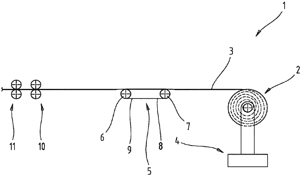
[0031] figure 1 A schematic diagram of a first embodiment of the manufacturing device 1 is shown. The manufacturing device 1 is configured for processing a wire 3 wound into a coil 2 .

[0032] The manufacturing device 1 comprises a receiving device 4 for receiving the wire reel 2 . Furthermore, an unwinding device 5 is formed, by means of which the wire 3 wound on the reel 2 can be p...


PUM


Abstract

The invention relates to a production system (1) for processing a wire material (3) wound to form a wire reel (2), in particular reinforcing steel. The production system (1) comprises a receiving device (4) for receiving the wire reel (2); an unreeling device (5) for removing the wire material (3) on the wire reel (2); and a processing device (10) for processing the removed wire material (3). Theunreeling device (5) comprises a conveying means (8) surrounding a first deflection roller (6) and a second deflection roller (7), wherein permanent magnets (16) are arranged on the conveying means (8) and an increased frictional connection can be established between a surface (13) of the wire material (3) and an outer surface (12) of the conveying means (8) by means of the permanent magnets (16).

Description

technical field [0001] The invention relates to a manufacturing plant for processing wire, in particular steel bars, wound into coils. Background technique [0002] It is known from the prior art to unwind steel bars wound into coils in production plants by driving the coils and actively unwinding the steel bars. It is additionally provided that a conveying device is formed, on which two rollers are arranged opposite each other, between which the wire is clamped. At least one of the two rollers is driven here and can exert a tensile force on the wire through a frictional fit between the roller and the wire in order to be able to continue conveying the wire unwound by said roller. [0003] The unwinding devices known from the prior art have the disadvantage that, especially for steel bars, relative movements between the drive roller and the wire can occur due to the rough surface structure of the steel bars or the surface with reliefs. Such conveying devices are therefore o...

Claims


Application Information

Patent Timeline
Patent Type & Authority Applications(China)
IPC IPC(8): B21C47/18B21C47/34B21C49/00B21D43/00B21D43/12B21F1/02B21F23/00B65G15/58B65H51/14B65H59/06
CPCB21F23/00B21C47/18B21C47/3483B21C49/00B21F1/02B65H51/14B65H51/20B65H2701/36B65H57/14
Inventor 胡贝特·拉佩斯托费尔
Owner 胡贝特拉佩斯托费尔
Why Eureka
Try Eureka