Biomass fuel forming device

A biomass fuel, molding device technology, applied in the direction of biofuel, waste fuel, fuel, etc., can solve problems such as jamming machine, and achieve the effect of reducing cost, convenient use and prolonging service life

Active Publication Date: 2018-11-27
江苏力得尔电力工程有限公司
View PDF6 Cites 3 Cited by
  • Summary
  • Abstract
  • Description
  • Claims
  • Application Information

AI Technical Summary

Problems solved by technology

However, the invention will jam when there are too many fillers and too thick

Method used


Image

  • Biomass fuel forming device
  • Biomass fuel forming device
  • Biomass fuel forming device

Examples


specific Embodiment approach 1

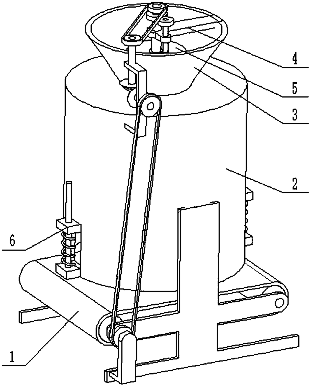
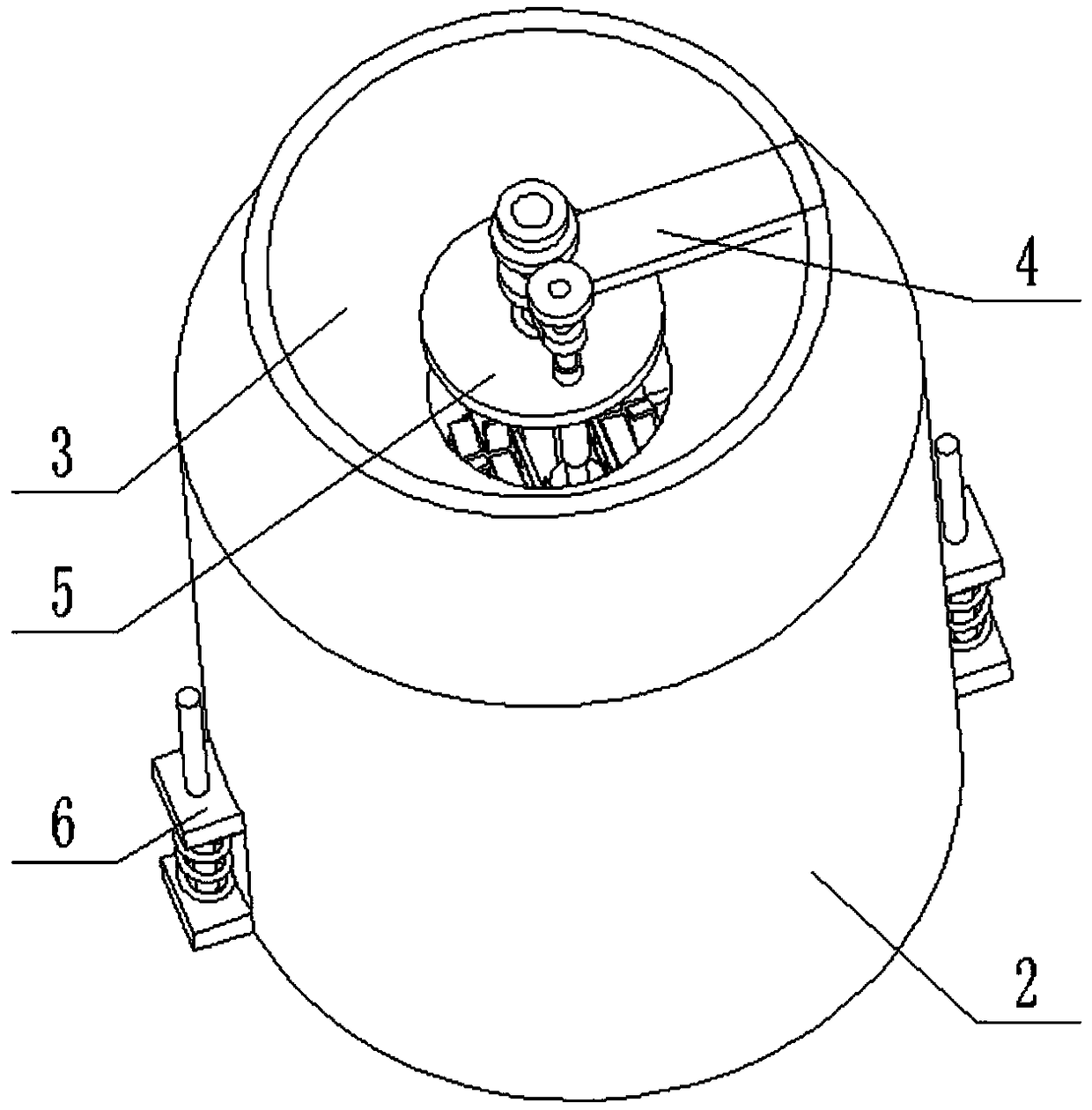
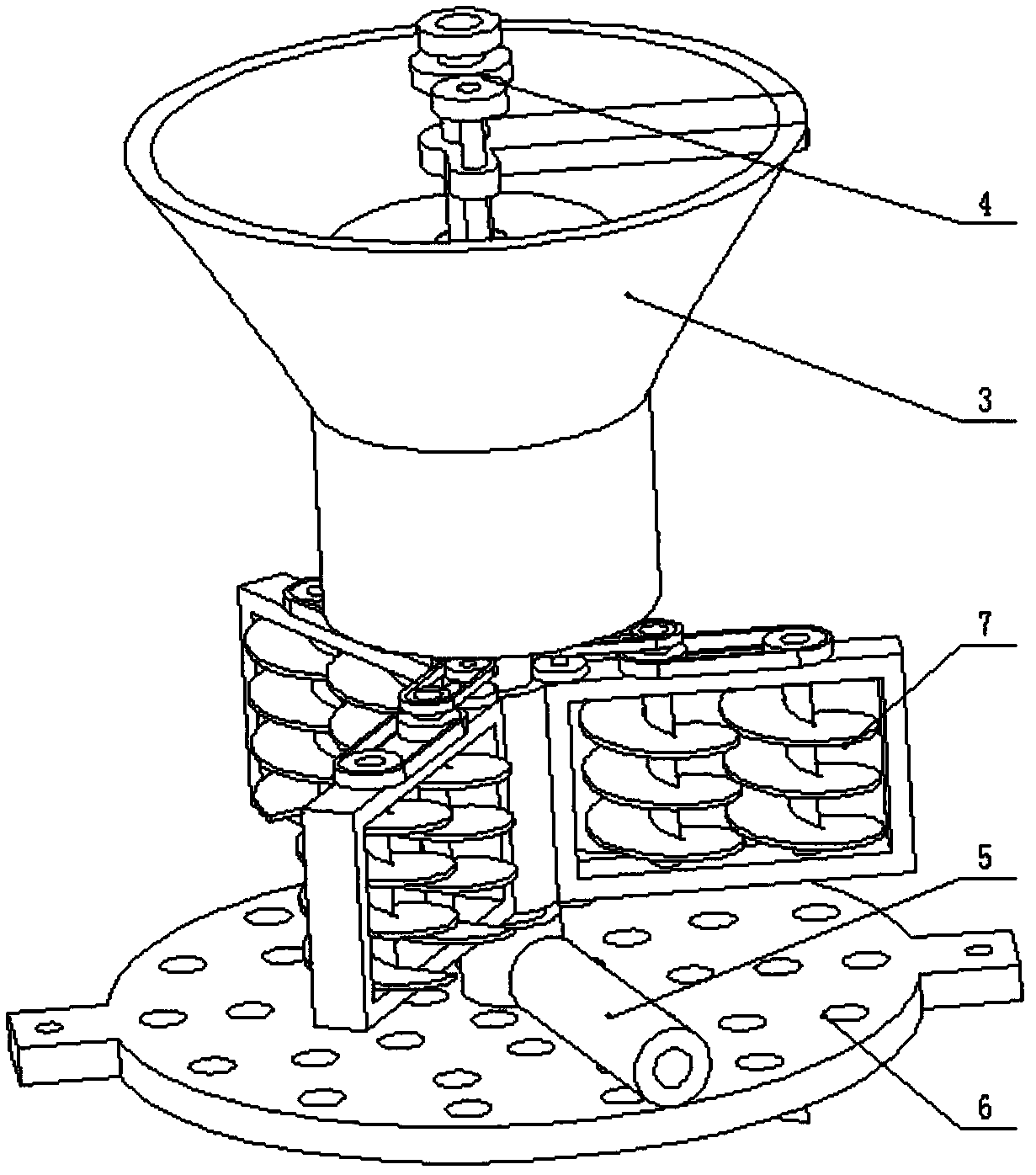
[0032] Combine below Figure 1-13 Describe this embodiment, a biomass fuel forming device, including a conveyor belt support seat assembly 1, a fuel forming cylinder 2, a raw material feeding assembly 3, a power transmission part 4, an overload prevention control assembly 5, a raw material forming plate 6 and a raw material stirring Assembly 7, the conveyor belt support seat assembly 1 includes a first roller shaft 1-1, a second roller shaft 1-2, a conveying roller 1-3, a conveyor belt 1-4, a support frame 1-5, The driving pulley 1-6 and the motor 1-7; the first roller shaft 1-1 and the second roller shaft 1-2 are fixedly connected with the conveying roller 1-3, and the two conveying rollers 1-3 There is a conveyor belt 1-4 connected between them, the two ends of the first roller shaft 1-1 are respectively connected to the left ends of the two support frames 1-5 through bearings with seats, and the two ends of the second roller shaft 1-2 are respectively It is connected to th...


PUM


Abstract

The invention relates to the technical field of biomass particle production, in particular to a biomass fuel forming device. Conveying rollers are fixedly connected to a first roller shaft and a second roller shaft, a conveying belt is connected between the two conveying rollers, two ends of the first roller shaft are rotationally connected to left ends of two supporting frames through plummer blocks respectively, and two ends of the second roller shaft are rotationally connected to right ends of the two supporting frames through plummer blocks respectively. A driving pulley is fixedly connected to the front end of the first roller shaft, and the front end of the first roller shaft is fixedly connected to an output shaft of a motor. When packing is excessive in quantity and thickness, feeding is halted to prevent jamming caused by overloading; after processing, raw materials can be timely discharged to avoid extrusion of a great quantity of finished products. In addition, convenience in use, stability in performance, operating efficiency improvement and production cost reduction are realized, labor intensity of operating personnel is relieved, and the service life of the device isprolonged.

Description

technical field [0001] The invention relates to the technical field of biomass particle production, in particular to a biomass fuel molding device. Background technique [0002] The existing patent number is CN201610947853.5 for a double-effect biomass fuel molding pelletizer, which discloses a double-effect biomass fuel molding pelletizer, including a body, a cylinder, a punch, a fuel molding template, a punch Head, lifting table, double-axis extension synchronous motor, transmission and disc cutter, a fixed block is arranged in the middle of the upper end of the body, a cylinder is fixedly installed on both sides of the fixed block, and the piston rod of each cylinder The head ends are fixedly connected with a punch, and each punch is respectively connected with the inner cavity of a punch, and the output end of the punch is fixedly connected with a fuel forming template, and a lifting platform is arranged in the body, so The lifting platform is provided with a motor fixi...

Claims


Application Information

Patent Timeline
Patent Type & Authority Applications(China)
IPC IPC(8): B01J2/20C10L5/44
CPCB01J2/20C10L5/445Y02E50/10Y02E50/30
Inventor 姜志远
Owner 江苏力得尔电力工程有限公司
Why Eureka
Try Eureka