Welding device for automobile safety air bag generator
A welding equipment and automobile safety technology, applied in welding equipment, welding equipment, laser welding equipment, etc., can solve the problems of low welding efficiency, high maintenance cost, large workpiece deformation, etc., and achieve high welding efficiency, low maintenance cost, and workpiece deformation. small deformation effect
- Summary
- Abstract
- Description
- Claims
- Application Information
AI Technical Summary
Problems solved by technology
Method used
Image

Examples
Embodiment Construction
[0026] Now in conjunction with the accompanying drawings, the preferred embodiments of the present invention will be described in detail.
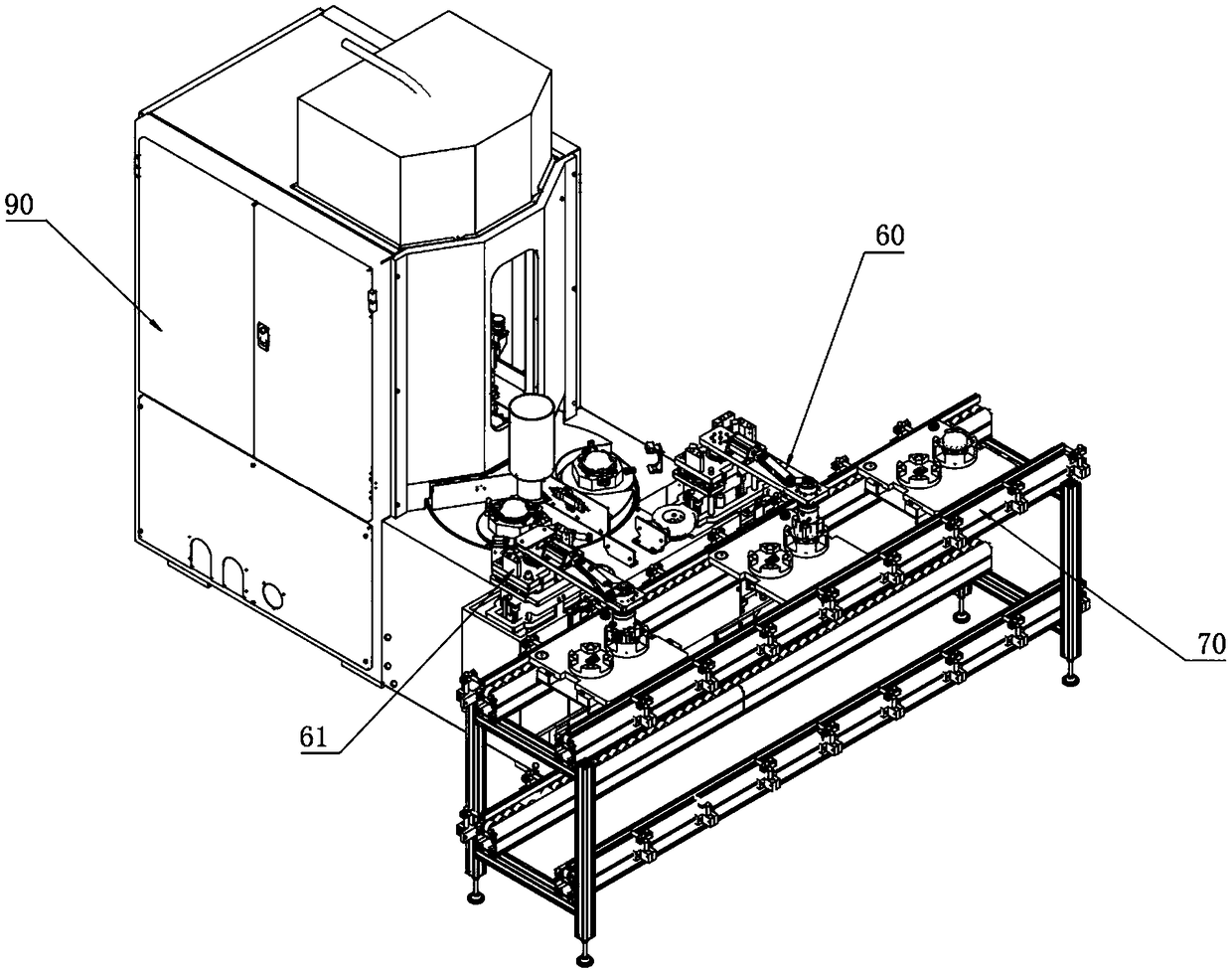
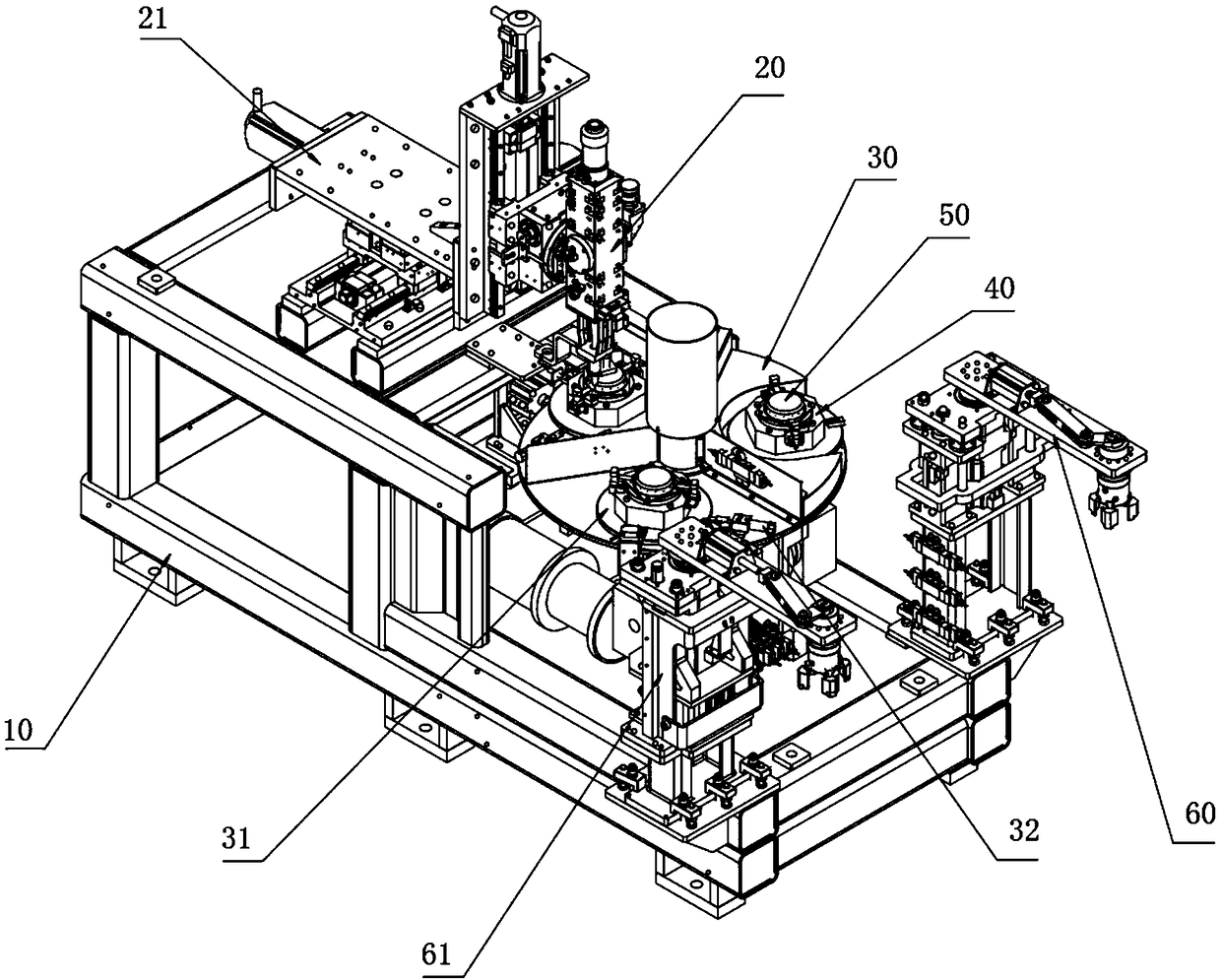
[0027] As shown in figure 2, a kind of welding equipment for automobile safety airbag generator of the present embodiment comprises a welding host, which includes a frame 10, a welding head 20 arranged on the frame 10, and a welding head 20 arranged below the welding head 20. The multi-station turntable 30, the multiple turntables 31 arranged on the multi-station turntable 30, the generator jig 40 arranged on the turntable 31 and rotating with the turntable 31. The generator (airbag generator) 50 on the generator jig 40 is driven to rotate together by the turntable 31, and then the generator 50 can be welded with the welding head 20 on the frame 10, and then the position of the turntable 31 can be adjusted by adding a The multi-station turntable 30 can carry out the loading and unloading process of the generator 50 at the same time when th...
PUM
 Abstract
Description
Claims
Application Information
PatSnap Eureka turns technology decisions into work you can execute. Powered by our Innovation Knowledge Graph, it runs expert workflows across engineering, life sciences, materials and intellectual property. Get your review-ready output in minutes.


