
Processing method of input shaft of integral high-precision hollow speed reducer

A processing method and input shaft technology, which are applied in the processing field of the input shaft (eccentric shaft) in the new hollow integrated high-precision reducer, can solve the problems affecting the use accuracy of the reducer, the return error of the input shaft, and the inability to manufacture the input shaft, etc. question

Inactive Publication Date: 2018-11-27
SHANDONG SHKE MACHINERY MFG +1
View PDF0 Cites 3 Cited by
  • Summary
  • Abstract
  • Description
  • Claims
  • Application Information

AI Technical Summary

Problems solved by technology

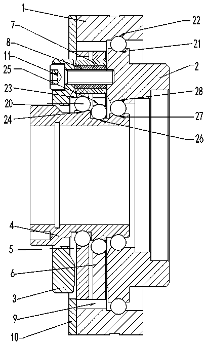
[0003] The existing hollow integrated high-precision reducer has a complex structure, including an input shaft, cycloidal wheel, rigid disc, needle roller, pin shaft, pin sleeve, ring gear, output shaft, and bearings. To achieve high-precision, High service life, very high machining accuracy requirements and installation accuracy requirements for each component
[0004] In the prior art, when manufacturing the reducer, the input shaft is processed first, and then the bearing is installed on the eccentric position. The position where the bearing is installed on the eccentric position on the input shaft is called the bearing position, and then the input shaft positioning bearing is inserted on the input shaft. The position where the positioning bearing is installed on the input shaft is also called the bearing position. The machining accuracy of the bearing position has corresponding requirements, and the concentricity of the bearing position must be high. Otherwise, the input shaft will produce a return error during use, which will affect the use accuracy of the reducer. , the shape error and position error caused by the bearing position processing and the assembly error caused by the installation of the bearing, these accumulated errors are important factors affecting the transmission accuracy and service life of the reducer, the same reason, the bearings also have these accumulated errors , so the importance of the processing accuracy requirements and assembly accuracy requirements of the input shaft can be imagined, but it is not yet possible to manufacture an input shaft that meets this requirement

Method used


Image

  • Processing method of input shaft of integral high-precision hollow speed reducer
  • Processing method of input shaft of integral high-precision hollow speed reducer
  • Processing method of input shaft of integral high-precision hollow speed reducer

Examples


Embodiment Construction

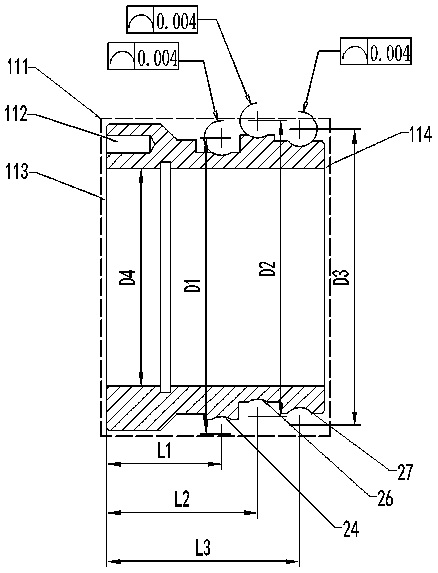
[0030] Examples such as Figure 1-5 As shown, the processing method of the input shaft of the hollow integrated high-precision reducer includes the following steps:

[0031] 1. Forging the input shaft blank 111;

[0032] 2. Machining the inner hole of the input shaft blank 111, and controlling the dimension D4, which is the diameter of the inner hole of the input shaft blank 111;

[0033] 3. Machining the first positioning plane 113 and the second positioning plane 114 of the input shaft blank 111;

[0034] Clamp the right end of the input shaft blank 111, process the first positioning plane 113 of the input shaft blank 111, and then process the second positioning plane 114 based on the inner hole of the input shaft blank 111 and the positioning plane 113;

[0035] The first positioning plane 113 is the left end surface of the input shaft blank 111 , and the second positioning plane 114 is the right end surface of the input shaft blank 111 .

[0036] 4. Process the position...


PUM


Abstract

The invention discloses a processing method of an input shaft of an integral high-precision hollow speed reducer. The processing method includes the steps of forging a blank of the input shaft, processing an inner bore of the blank of the input shaft, processing a first positioning plane and a second positioning plane of the blank of the input shaft, processing a positioning pin hole in the blankof the input shaft, clamping and assembling the blank of the input shaft by one step, and finishing a first outer race, a second outer race and a third outer race of the input shaft respectively. Without weakening various functions of the speed reducer, the processing method, aiming to improve service life of the input shaft, reduces error accumulation during assembling by reducing number of parts, eliminates three bearing stations of the conventional input shaft, processes the inner races of bearings onto the input shaft directly to eliminate assembly error between the bearings and the bearing stations, and accordingly improves precision.

Description

technical field [0001] The invention relates to the technical field of high-precision reducer processing, in particular to a processing method for an input shaft (eccentric shaft) in a novel hollow integrated high-precision reducer. Background technique [0002] The hollow integrated high-precision reducer has the advantages of small size, light weight, stable transmission, low noise, high motion precision, large transmission ratio, and high carrying capacity, and is widely used in electronics, robotics, aerospace and other industries. [0003] The existing hollow integrated high-precision reducer has a complex structure, including an input shaft, cycloidal wheel, rigid disc, needle roller, pin shaft, pin sleeve, ring gear, output shaft, and bearings. To achieve high-precision, High service life, the machining accuracy requirements and installation accuracy requirements of each component are very high. [0004] In the prior art, when manufacturing the reducer, the input sha...

Claims


Application Information

Patent Timeline
IPC IPC(8): B23P15/14
CPCB23P15/14
Inventor 汤承龙谭立勇段星光鲁守银赵洪华李国才付同军李祥奎艾长胜王俊明
Owner SHANDONG SHKE MACHINERY MFG
Learn More