Double-wall drill pipe

A double-wall drill pipe and short-circuit technology, which is used in drill pipe, drill pipe, earth-moving drilling, etc., can solve the problems of reducing the service life of the sealing ring, damage to the sealing ring of the sealing ring, squeezing, etc., and improve the sealing pressure. Capability and reliability, seal pressure rating and reliability improvement, effect of increasing service life

Pending Publication Date: 2018-11-27
黄桂霞
View PDF0 Cites 4 Cited by
  • Summary
  • Abstract
  • Description
  • Claims
  • Application Information

AI Technical Summary

Problems solved by technology

However, the double-walled drill pipe with this structure has the following problems: ① Both the inner and outer drill pipes are relatively long, and their length can reach about 10 m. If the gap between the joints is too large, the sealing ring under high pressure will be easily damaged by the assembly sealing ring squeezed into the gap between the male joint and the female joint, which will reduce the pressure bearing capacity and reliability of the seal; ② Frequent disassembly and assembly of the drill pipe may cause the sealing ring to curl and crushing damage, reducing the pressure bearing capacity and reliability of the seal; ③Due to the space limitation between the inner and outer pipes, the inner pipe needs to be suspended on the upper step of the outer pipe. Due to the small step surface and the double-walled drill pipe, the inner pipe vibrates up and down during the process It is easy to cause the suspension step to fail, and the inner and outer tubes are misaligned up and down; the up and down vibration of the inner tube will also greatly reduce the service life of the sealing ring
The failure of the sealing ring will lead to the failure of the double-wall drill pipe drilling method, which seriously hinders the popularization and application of the double-wall drill pipe drilling technology

Method used


Image

  • Double-wall drill pipe
  • Double-wall drill pipe
  • Double-wall drill pipe

Examples


Embodiment 1

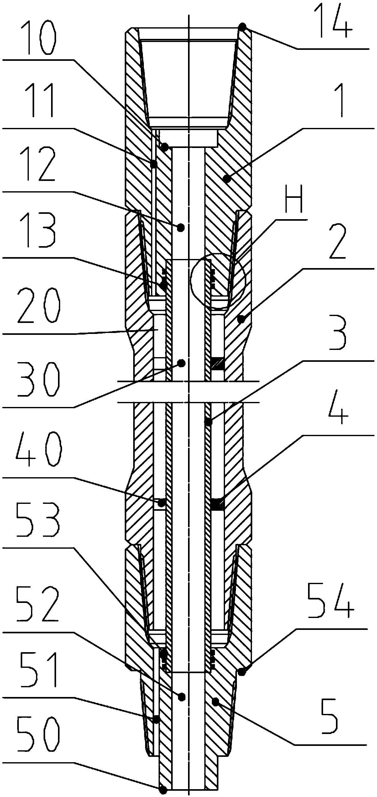
[0038] Such as figure 1 As shown, the double-walled drill pipe includes an upper short connection 1, an outer pipe 2 and a lower short connection 5 sequentially connected from top to bottom, and an inner pipe 3 sleeved in the center hole of the outer pipe 2; wherein,

[0039] The upper short connection 1 is a cylindrical structure, the inner wall of the top end is processed with an internal thread concentric with the outer cylindrical surface, the outer wall of the bottom end is processed with an outer thread concentric with the outer cylindrical surface, and the end surface located below the internal thread is respectively along the In the axial direction, there are a central channel A12 and an eccentric channel A11 that penetrate up and down;

[0040] The outer pipe 2 is a conventional single-wall drill pipe, with internal threads processed on the inner wall of the top end and external threads processed on the outer wall of the bottom end; The threads cooperate with each ot...

Embodiment 2

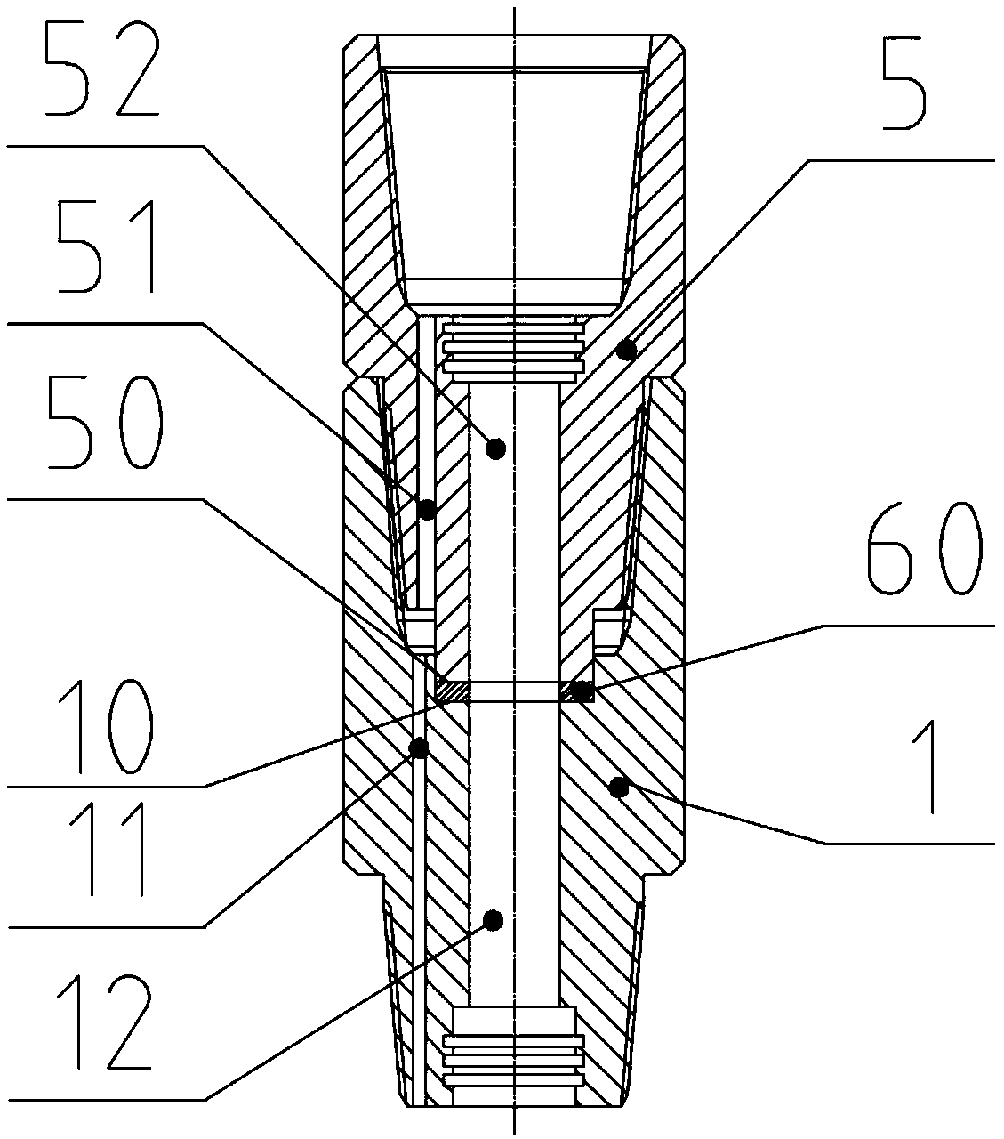
[0047] Such as image 3 As shown, the structure of the double-walled drill rod is basically the same as that of the double-walled drill rod in Example 1, the difference is that: between the shoulder surface B10 and the shoulder surface D50 of the upper short-circuit 1 is provided with a The seal C60 adapted to the shoulder surface 50 makes the seal between the shoulder surface B10 and the shoulder surface D50 form a seal through the seal C60; wherein, the seal C60 is a combined sealing gasket that is vulcanized by rubber and metal ring .

Embodiment 3

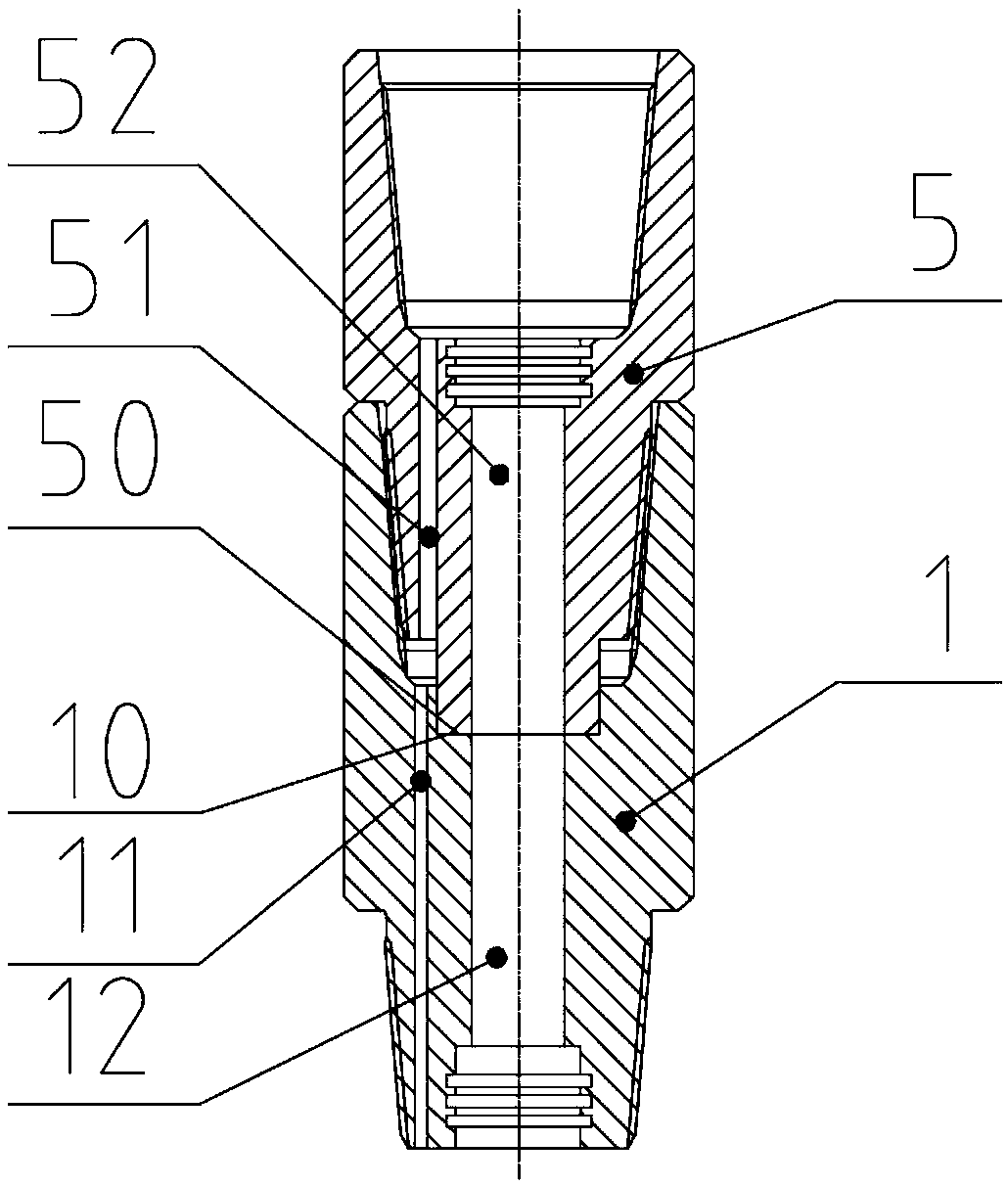
[0049] Such as Figure 4 As shown, the structure of the double-walled drill pipe is basically the same as that of the double-walled drill pipe in Example 1, except that the end face located below the internal thread of the upper joint 1 is processed as a platform that cooperates with the annular shoulder surface D50 Shoulder surface B10, and an annular groove with a rectangular ring cross section is opened on the shoulder surface B10, and a rectangular sealing ring C60 is arranged in the annular groove, so that the rectangular sealing ring passes between the shoulder surface B10 and the shoulder surface D50 A seal is formed; wherein, the rectangular sealing ring is a rectangular rubber ring.


PUM


Abstract

The invention discloses a double-wall drill pipe which comprises an upper pup joint, an outer pipe, a lower pup joint and an inner pipe, wherein the upper pup joint, the outer pipe and the lower pup joint are sequentially connected in a threaded manner from top to bottom, and the inner pipe is arranged in a center duct of the outer pipe. Center ducts and eccentric ducts are axially formed in the upper pup joint and the lower pup joint, the inner pipe is mounted in the outer pipe in a gapped mode to form a double-wall pipe with a center duct and an annular duct, two ends of the double-wall pipeare fixed onto walls of the center ducts of the upper pup joint and the lower pup joint, the center ducts of the upper pup joint and the lower pup joint are communicated with the center duct of the inner pipe to form a first liquid passing channel, the eccentric ducts of the upper pup joint and the lower pup joint are communicated with the annular duct formed between walls of the inner pipe and the outer pipe to form a second liquid passing channel, and a shoulder seal is formed between two components in threaded connection, so that the first liquid passing channel is not connected with the second liquid passing channel. According to the double-wall drill pipe, up-down bounce of the inner pipe in the use process is effectively prevented, and sealing pressure-bearing capacity and reliability between the inner pipe and the outer pipe which are long can be greatly improved.

Description

technical field [0001] The invention relates to the technical field of drilling, in particular to a double-wall drill pipe. Background technique [0002] The double-wall drill pipe drilling method refers to the method of drilling with double-wall drill pipe and other auxiliary equipment, mainly including low-pressure drilling, central sampling drilling, RDM technology and double-wall gas-filled drilling. This method has been paid attention to and popularized in the fields of geology and mining and oil drilling. [0003] At present, the double-wall drill pipe commonly used in the double-wall drill pipe drilling method is composed of an inner pipe and an outer pipe. They are connected by threads, and the inner tubes are connected by inserting a radial sealing structure to prevent fluid communication between the two channels. However, the double-walled drill pipe with this structure has the following problems: ① Both the inner and outer drill pipes are relatively long, and th...

Claims


Application Information

Patent Timeline
IPC IPC(8): E21B17/00E21B17/042F16J15/06
CPCE21B17/00E21B17/042F16J15/06
Inventor 黄桂霞刘凯
Owner 黄桂霞
Why Eureka
Try Eureka