SHPB device and method for achieving ultra-high controllable strain rate impact

A strain rate and fixing device technology, applied in the field of material dynamic mechanical properties research, can solve the problems of repeated calibration, low debugging work efficiency, and difficult to determine the corresponding relationship, so as to reduce device cost and processing difficulty, improve debugging work efficiency, The effect of ensuring the coaxiality of the device

Pending Publication Date: 2018-11-27
UNIV OF JINAN
View PDF7 Cites 3 Cited by
  • Summary
  • Abstract
  • Description
  • Claims
  • Application Information

AI Technical Summary

Problems solved by technology

The disadvantage of this method is that in order to ensure the complete incident waveform and reflected waveform, the length of the incident rod is much longer than twice the output rod. In actual processing, the processing of the incident rod is more difficult, which leads to higher processing costs of the device.
Secondly, the device uses an air gun as the driving source. Since the relationship between the impact velocity and the air pressure is difficult to determine, the strain rate during the test cannot be accurately controlled. It takes multiple trials to achieve the required strain rate.
In addition, the separate Hopkinson pressure rod device uses a combined reference guide rail. When replacing the barrel or rod system, the installation of the combined guide rail needs to ensure that the two sliders are aligned with the chute on the guide rail at the same time. The installation process needs to be repeatedly calibrated. , low debugging efficiency

Method used


Image

  • SHPB device and method for achieving ultra-high controllable strain rate impact
  • SHPB device and method for achieving ultra-high controllable strain rate impact
  • SHPB device and method for achieving ultra-high controllable strain rate impact

Examples


Embodiment Construction

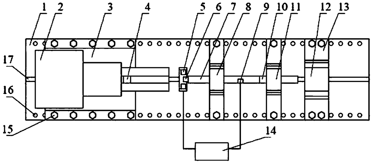
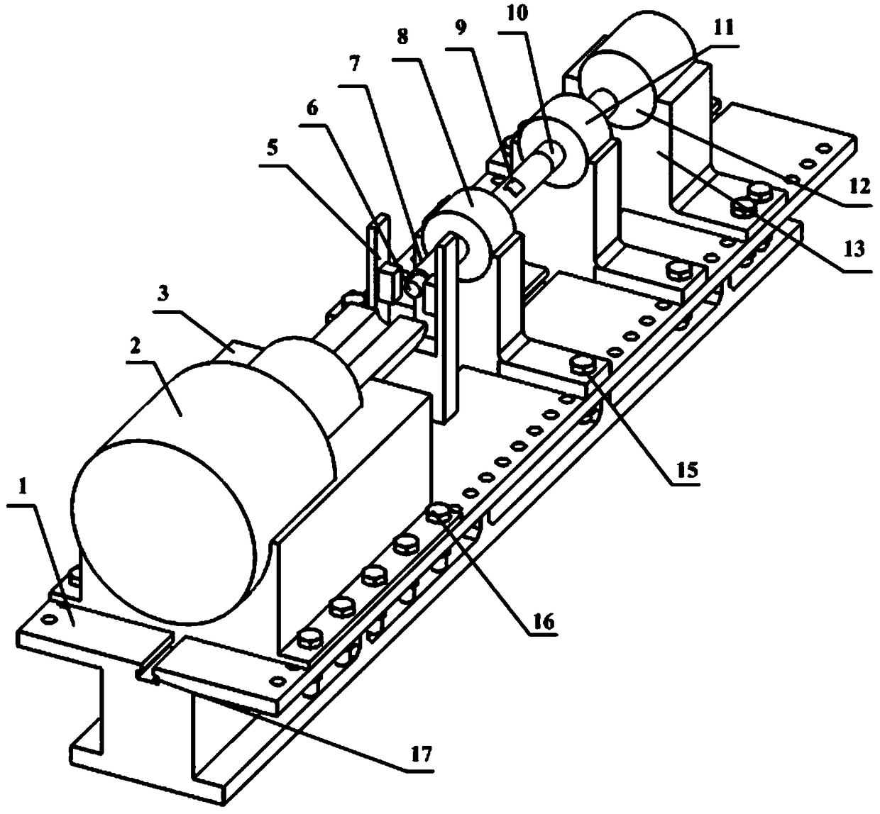
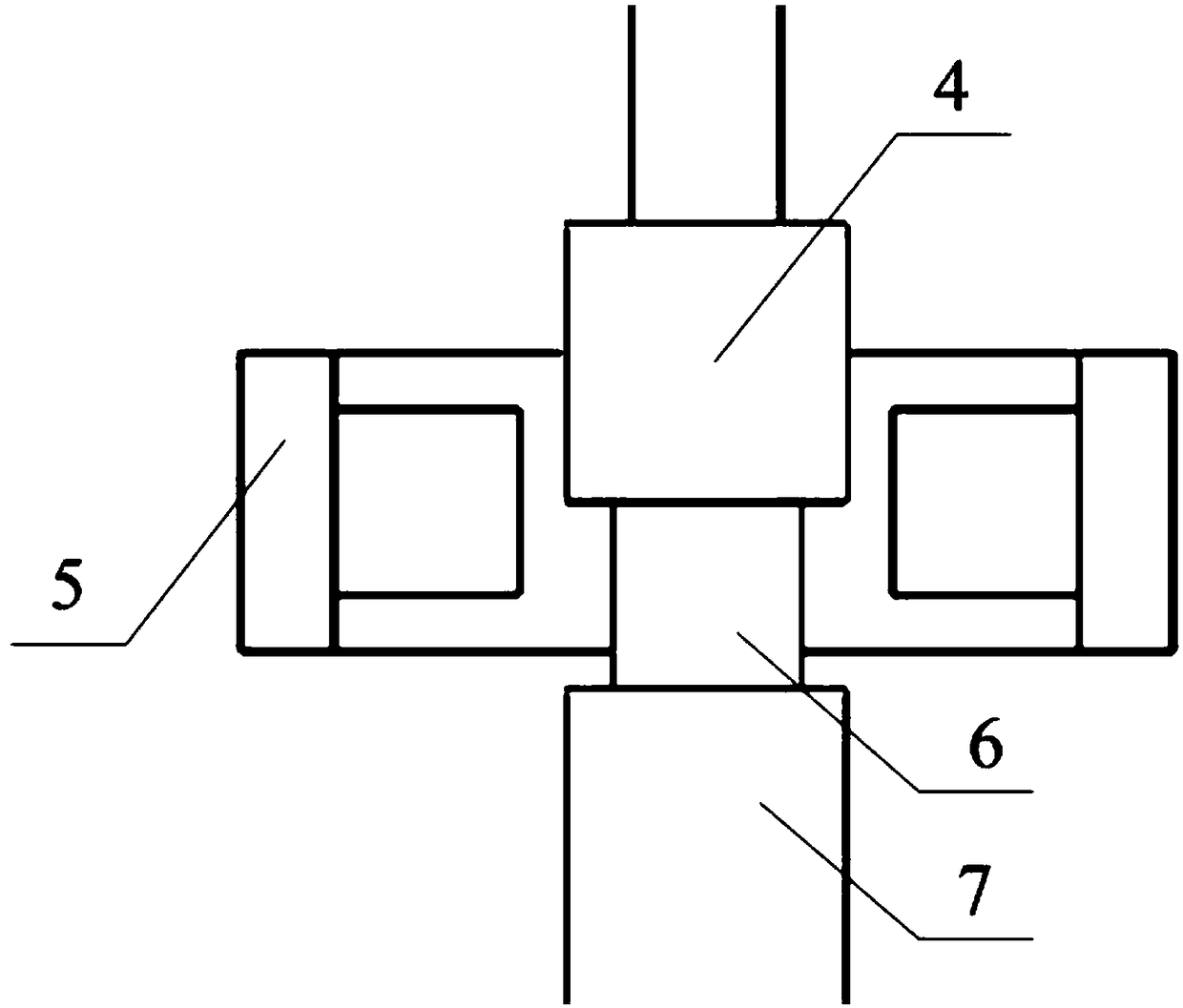
[0018] The present invention is a SHPB device and method for realizing ultra-high controllable strain rate impact, comprising a guide rail 1 with a T-shaped groove, a light gas cannon loading mechanism 2, a light gas cannon base 3, a marble 4, and a magnetoelectric particle velocity Measuring device 5, test piece 6, output rod 7, output rod fixing device 8, strain gauge 9, absorbing rod 10, absorbing rod fixing device 11, damper 12, damper fixing device 13, data processing system 14 and other structures, among which , light gas gun base 3, marble 4, magnetoelectric particle velocity measuring device 5, test piece 6, output rod 7, output rod fixing device 8, strain gauge 9, absorbing rod 10, absorbing rod fixing device 11, damper 12 , The damper fixing devices 13 are distributed sequentially along the axis.

[0019] The magnetoelectric particle velocity measuring device 5 is located between the test piece and the light gas cannon loading mechanism 3. When the marble 4 hits the ...


PUM


Abstract

The invention discloses an SHPB device and method for achieving ultra-high controllable strain rate impact. The device comprises structures of a guiding rail with a T-shape groove, a light gas gun loading mechanism, a light gas gun base, a bullet, a magnetic electricity type particle velocity measuring device, a testing member, an output rod, an output rod fixing device, a strain piece, an absorbing rod, an absorbing rod fixing device, a damping device, a damping device fixing device, a data processing system and the like; the device is characterized in that the impacting on the testing memberof an incidence rod is replaced with the direct impacting on the testing member by the bullet, the particle velocity of the testing member at the incidence end is measured by the magnetic electricitytype particle velocity measuring device, the average stress, strain rate and strain of the testing member are obtained according to unidimensional stress wave assumption and uniform distribution assumption of the stress/strain of a short testing member along the length of the short testing member, and the coaxiality of the device is ensured by the T-shaped groove and bolt connection cooperative action. By means of the device and the method, controllable and ultra-high strain rate (107s<-1> scale) loading can be achieved within a larger range (104-107s<-1> scale), the debugging efficiency canbe improved, the structure is simple, and the dynamic mechanical performance of a material under the ultra-high strain rate is obtained conveniently and rapidly.

Description

technical field [0001] The invention relates to the field of research on dynamic mechanical properties of materials, in particular to a SHPB device and method for ultra-high controllable strain rate impact. Background technique [0002] With the emergence of high-speed cutting technology, it is particularly important to study the dynamic mechanical properties of materials under high strain rate or even ultra-high strain rate (high-speed cutting conditions). The Hopkinson compression rod device is the main device for studying the dynamic mechanical properties of materials, and can obtain various dynamic mechanical parameters of materials under high strain rates. Due to the wide application of aerospace light alloys such as titanium and aluminum in high-speed cutting, the measurement of their dynamic mechanical properties should be carried out at ultra-high strain rates. However, the current Hopkinson compression bar device can only realize the dynamic mechanical properties m...

Claims


Application Information

Patent Timeline
Patent Type & Authority Applications(China)
IPC IPC(8): G01N3/02G01N3/307
CPCG01N3/02G01N3/307
Inventor 周彬付秀丽
Owner UNIV OF JINAN
Why Eureka
Try Eureka