Implantation instrument for preventing regurgitation jet and delivery system therefor

A valve and device technology, applied in the field of implanted devices and their delivery systems, can solve problems such as complex physiological environment, implanted device failure, oxygen delivery function decline, etc., to achieve enhanced anchoring effect, enhanced anchoring effect, and reduced operation difficulty Effect

Active Publication Date: 2018-11-30
NINGBO JENSCARE BIOTECHNOLOGY CO LTD
View PDF9 Cites 3 Cited by
  • Summary
  • Abstract
  • Description
  • Claims
  • Application Information

AI Technical Summary

Problems solved by technology

Mitral regurgitation can be divided into the following two types: 1. Rheumatic heart mitral regurgitation, mainly caused by mitral regurgitation, can cause blood to flow in reverse, so that different blood can mix, causing heart pumping blood, decreased oxygen delivery
The main reason is that the mitral valve ring and tricuspid valve ring have special physiological structures, and there is a complex physiological environment below the valve ring, making it very difficult to accurately position and fix the product
In addition, the degree and location of valve prolapse are different. For example, some patients have regurgitation caused by anterior valve prolapse, and some patients have regurgitation caused by combined valve disease. It also interferes with the physiological structure of the remaining normal mitral valve, and the adaptability of the lesion is insufficient
At the same time, the complex blood flow movement makes the implanted device easy to adhere to the autologous tissue, making the implanted device ineffective, or even generating thrombus, which will be life-threatening if it falls

Method used


Image

  • Implantation instrument for preventing regurgitation jet and delivery system therefor
  • Implantation instrument for preventing regurgitation jet and delivery system therefor
  • Implantation instrument for preventing regurgitation jet and delivery system therefor

Examples


specific Embodiment 1

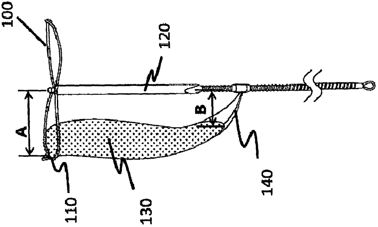
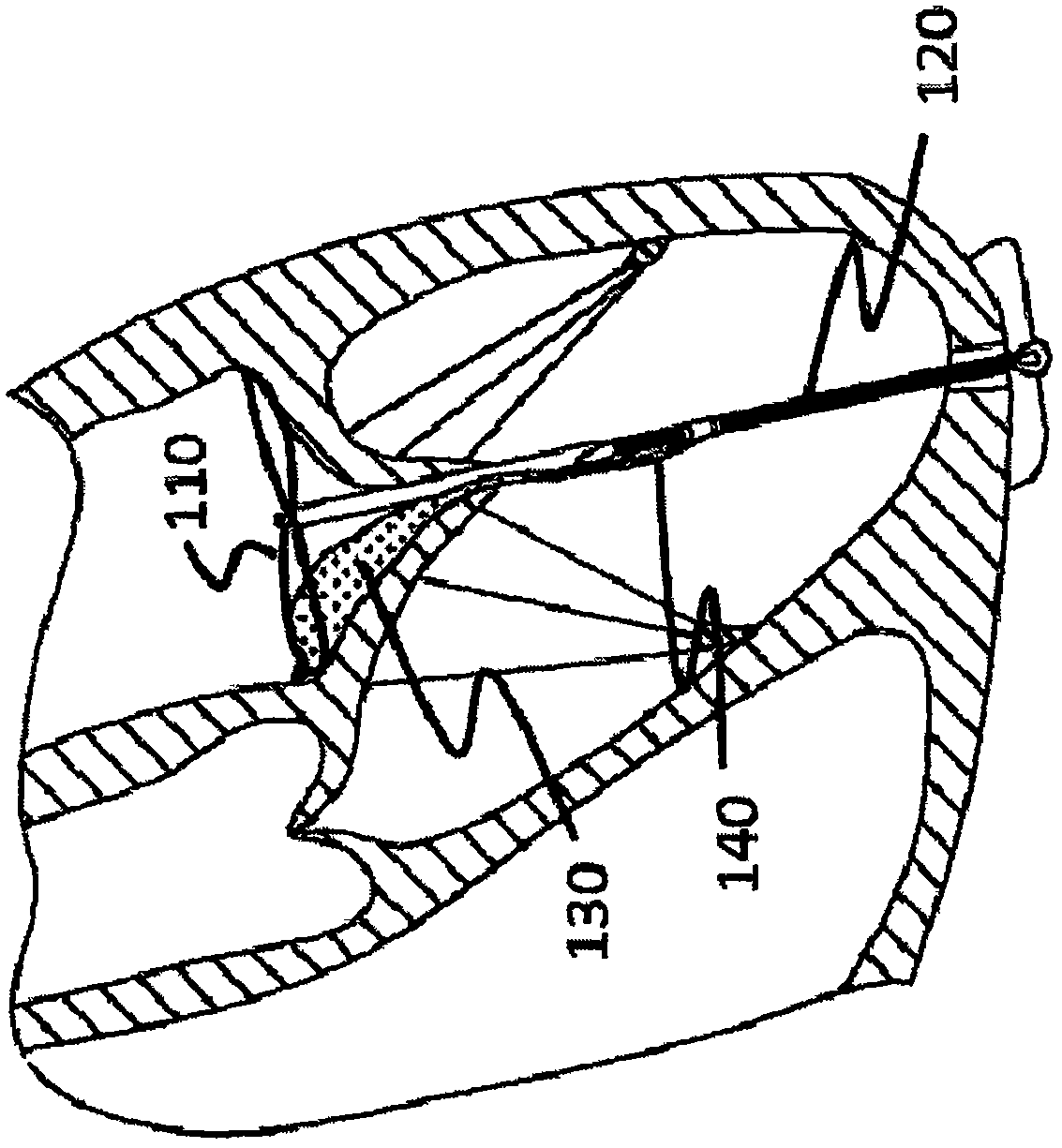
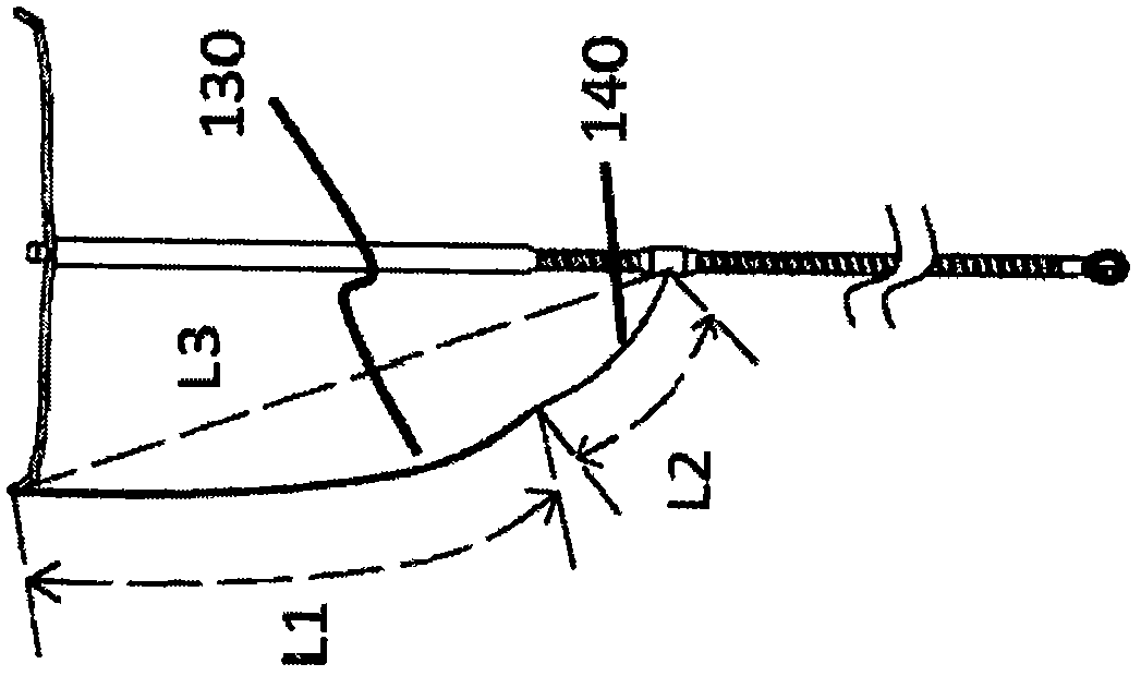
[0075] like Figure 1a and Figure 1bAs shown, an implantation device 100 for preventing valve regurgitation includes a distraction mechanism 110, a core 120 and a closure aid 130, the distraction mechanism 110 is connected to the distal end of the core 120, The distal end of the closing aid 130 is connected to the opening mechanism 110, and the closing aid 130 is flexible. In a free state, the opening aid 110 is located in the patient's atrium. The closing aid 130 Located between the patient's own valve leaflets, the proximal end of the closure aid 130 is provided with a limiter 140, the distal end of the limiter 140 is connected to the proximal part of the closure aid 130, the limiter The proximal end of the member 140 is connected to the core member 120, so that the closure aid 130 can fit the core member 120 in a free state without overturning, and the distal end of the closure aid 130 is connected to the core member 120. The vertical distance A of the core 120 is greater...

specific Embodiment 2

[0086] like Figure 9a and Figure 9b As shown, an implantation device 200 for preventing valve regurgitation includes a distraction mechanism 210, a core 220 and a closure aid 230, the distraction mechanism 210 is connected to the distal end of the core 220, The distal end of the closing aid 230 is connected to the opening mechanism 210, and the closing aid 230 is flexible. In a free state, the opening aid 210 is located in the patient's atrium. The closing aid 230 Located between the patient's own valve leaflets, the proximal end of the closure aid 230 is provided with a limiter 240, the distal end of the limiter 240 is connected to the proximal part of the closure aid 230, the limiter The proximal end of the member 240 is fixed on the patient's apex tissue, so that the closing aid 230 can fit the core 220 in a free state without turning over, and the proximal end of the core 220 is fixed on the patient's apex organizationally.

[0087] like Figure 9b and Figure 9c As...

specific Embodiment 3

[0095] like Figure 16a As shown, an implant instrument 300 for preventing valve regurgitation includes a distraction mechanism 310, a core 320 and a closure aid 330, the distraction mechanism 310 is connected to the distal end of the core 320, The intersection of the core 320 and the plane where the expansion mechanism 310 is located is located at the midpoint of the expansion mechanism 310, the distal end of the closing aid 330 is connected to the expansion mechanism 310, and the auxiliary closure 330 is connected to the expansion mechanism 310. The closing member 330 is flexible. In the free state, the expansion mechanism 310 is located in the patient's atrium, the closing aid 330 is located between the patient's own valve leaflets, and the proximal end of the closing aid 330 is provided with a limiting member 340 , the distal end of the limiting member 340 is connected to the proximal part of the closing aid 330, and the proximal end of the limiting member 340 is fixed on ...


PUM


Abstract

The invention relates to an implantation instrument for preventing regurgitation jet and a delivery system thereof, wherein the implantation instrument comprises a distracting mechanism, a core element and a closure assisting element, wherein the distracting mechanism is connected with the core element; the distal end of the closure assisting element is connected with the distracting mechanism; and the closure assisting element is flexible, in a free state, the distracting mechanism is partially or wholly positioned in the atrium of a patient, or the distracting mechanism is fully positioned in the autologous compartment valve ring of the patient. The closure assisting element is partially arranged between the autologous valve leaflets of the patient, and the proximal end of the closure assisting element is provided with a limit element. The distal end of the limit element is connected to the closure assisting element, the proximal end of the limit element is connected to the core element or fixed to the heart tissue of the patient, and the closure assisting element can partially attach to the core element as the autologous valve is closed. At least one end of the core element is fixed to the heart tissue of the patient. The instrument has the advantages of accurate positioning, convenient operation, firm anchoring, less long-term thrombus formation, and less adhesion to the original tissue and is capable of coping with various degrees and positions of pathological changes.

Description

Technical field: [0001] The invention belongs to the field of medical devices, and in particular relates to an implant device for preventing valve regurgitation and a delivery system thereof. Background technique: [0002] Normal mitral valve closing function depends on the complete structure and normal function of the valve leaflets, valve ring, chordae, papillary muscles, and left ventricle. Structural and functional abnormalities in any of these five parts can cause mitral regurgitation. With mild reflux, the patient has only mild exertional dyspnea. Severe reflux (such as papillary muscle rupture) will soon lead to acute left heart failure, and even cardiogenic shock. Mitral regurgitation can be divided into the following two types: 1. Rheumatic heart mitral regurgitation, mainly caused by mitral regurgitation, can cause blood to flow in reverse, so that different blood can mix, causing heart pumping Blood, oxygen delivery function decreased. 2. Non-rheumatic mitral ...

Claims


Application Information

Patent Timeline
Patent Type & Authority Applications(China)
IPC IPC(8): A61F2/24
CPCA61F2/2436A61F2/2442A61F2/2466A61F2/2469A61F2210/0014
Inventor 吕世文李毅斌陈志曹鹏
Owner NINGBO JENSCARE BIOTECHNOLOGY CO LTD
Why Eureka
Try Eureka