Insulation tank car insulation system

An insulation system and technology for tank cars, which are applied to tank cars, transport passenger cars, railway car body parts, etc. Weight, the effect of reducing the heat leakage rate

Active Publication Date: 2019-08-02
辽宁金碧科创集团有限公司
View PDF7 Cites 0 Cited by
  • Summary
  • Abstract
  • Description
  • Claims
  • Application Information

AI Technical Summary

Problems solved by technology

[0007] The purpose of the present invention is to provide a thermal insulation system for thermal insulation tank cars with reasonable structure and reliable use, which can effectively solve the problem of heat leakage in existing thermal insulation tank vehicles, effectively block heat conduction, reduce heat leakage rate, and ensure the thermal insulation effect of the tank body At the same time, under the premise of ensuring the heat preservation effect, the weight of the heat preservation structure of the tank head is reduced, the difficulty of production is reduced, and the production cost is reduced

Method used


Image

  • Insulation tank car insulation system
  • Insulation tank car insulation system
  • Insulation tank car insulation system

Examples


Embodiment Construction

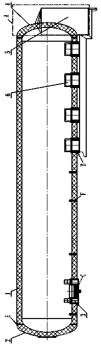
[0037] Such as Figure 1-Figure 8 , Figure 12 , Figure 13 As shown, the heat preservation tank car heat preservation system includes a tank body heat preservation structure sandwiched between the inner and outer tank bodies and a secondary heat preservation structure connected with the tank body heat preservation structure. The secondary thermal insulation structure consists of the secondary thermal insulation structure A of the tank body head, the secondary thermal insulation structure B of the V-shaped beam of the tank body, the secondary thermal insulation structure C of the tank traction plate, and the thermal insulation structure of the tank body located at the metal connector of the tank body. Structure E composition.

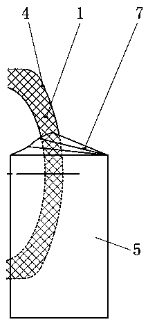
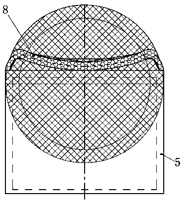
[0038] Among them, see figure 2 , image 3 The secondary heat preservation structure A of the tank head includes a rear head body 4 and a valve box, the valve box surrounds the middle and lower part of the rear head body 4, and the valve box is com...


PUM


Abstract

The invention relates to a novel heat preservation system of a heat preservation tank car. The novel heat preservation system comprises a tank body heat preservation structure camped between an innertank body and an outer tank body, and a secondary heat preservation structure connected with the tank body heat preservation structure. The novel heat preservation system is technically characterizedin that the secondary heat preservation structure is composed of a tank body end socket secondary heat preservation structure, a tank body V-shaped beam secondary heat preservation structure, a tank body traction disc secondary heat preservation structure and a tank body heat insulation structure located on a tank body metal connector. The novel heat preservation system effectively solves the problem that heat is leaked out of a tank body of an existing heat preservation tank car, heat conduction is effectively blocked, the heat leakage rate is reduced, and therefore the heat preservation effect of the tank body is guaranteed. Meanwhile, on the premise of guaranteeing the heat preservation effect, the weight of the tank body end socket heat preservation structure is reduced, the productiondifficulty is reduced, and production cost is reduced.

Description

technical field [0001] The invention relates to a thermal insulation structure of a closed container such as a tank body, in particular to a thermal insulation system for a thermal insulation tank car. Background technique [0002] At present, the thermal insulation structure of the thermal insulation tanker is mainly the tank insulation layer sandwiched between the inner and outer tanks. The tank insulation layer is used to prevent heat loss in the tank. However, the following problems have been found after use: [0003] 1. There is generally a discharge valve under the head of the tank body. In order to achieve the purpose of heat preservation, a valve box is usually provided on the outer cover of the head. In the traditional heat preservation structure, the head and valve box are generally made of carbon steel or stainless steel. In addition, the valve box adopts a fully enclosed structure, that is, the head is completely covered in it. Therefore, the thermal insulation s...

Claims


Application Information

Patent Timeline
Patent Type & Authority Patents(China)
IPC IPC(8): B65D88/74B65D90/00
CPCB65D88/74B65D90/00
Inventor 王迪唐建佟昊
Owner 辽宁金碧科创集团有限公司
Why Eureka
Try Eureka