Heat treatment device for crankshaft processing device

A heat treatment device and crankshaft processing technology, applied in heat treatment furnaces, heat treatment equipment, quenching devices, etc., can solve the problems of difficult installation, complex structure, inability to effectively recover oil and secondary quenching, etc., to improve efficiency and shorten time. Effect

Inactive Publication Date: 2018-11-30
江苏太宝龙实业有限公司
View PDF1 Cites 2 Cited by
  • Summary
  • Abstract
  • Description
  • Claims
  • Application Information

AI Technical Summary

Problems solved by technology

[0004] The structure of the above-mentioned patent is complicated, the installation is not easy, and the oil quality cannot be recovered effectively for secondary quenching

Method used


Image

  • Heat treatment device for crankshaft processing device
  • Heat treatment device for crankshaft processing device
  • Heat treatment device for crankshaft processing device

Examples


Embodiment 1

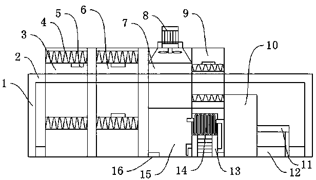
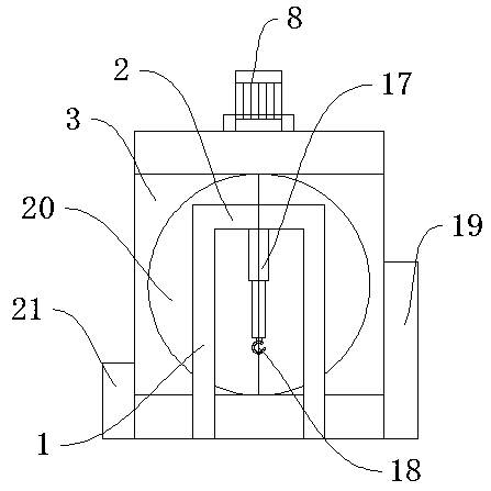
[0027] Such as Figure 1-Figure 3 As shown, a heat treatment device for crankshaft processing includes a normalizing chamber 3, an annealing chamber 6, and a quenching chamber 7. A support frame 1 is provided on one side of the normalizing chamber 3, and an insulating door 20 is provided on one side of the normalizing chamber 3. , a movable frame 2 is arranged above the support frame 1, a heater 4 is arranged above the inside of the normalizing chamber 3, a telescopic cylinder 17 is arranged below the movable frame 2, a hook 18 is arranged below the telescopic cylinder 17, and a same setting is arranged below the inside of the normalizing chamber 3 There is a heater 4, a first-type temperature sensor 5 is arranged under the heater 4, the model of the first-type temperature sensor 5 is TR / 02010, an annealing chamber 6 is arranged on the other side of the normalizing chamber 3, and an annealing chamber 6 is arranged on one side There is a quenching chamber 7, a fan 8 is arranged...

Embodiment 2

[0029] The difference between this embodiment and Embodiment 1 is that in this embodiment, the quenching chamber 15 and the high-pressure water pump 13 are connected together through threads, the high-pressure water pump 13 and the radiator 14 are connected together through threads, and the radiator 14 and the quenching chamber 15 are connected together through threaded together.

[0030] Specifically, such setting can lower the temperature of the medium in the quenching chamber 15 and shorten the heat treatment time.

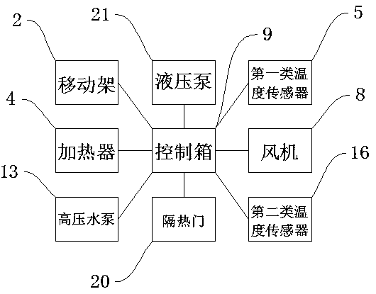
[0031]The working principle of the present invention is: after the crankshaft is hung on the hook 18 during use, the normalizing temperature, annealing temperature and tempering temperature are set by operating the control box 19. After setting, the control box 19 controls the moving frame 2 to move Drive the crankshaft to enter the normalizing chamber 3 for normalizing. After normalizing, the crankshaft enters the annealing chamber 6 for annealing. The first ...


PUM

PropertyMeasurementUnit
thicknessaaaaaaaaaa

Abstract

The invention discloses a heat treatment device for a crankshaft processing device. The heat treatment device for the crankshaft processing device comprises a normalizing chamber, an annealing chamberand a quenching chamber, wherein a support frame is arranged on one side of the normalizing chamber; a heat insulation door is arranged on one side of the inner part of the normalizing chamber; a moving frame is arranged above the support frame; a heater is arranged on the upper part of the inner part of the normalizing chamber; a telescopic cylinder is arranged under the moving frame; a pothookis arranged under the telescopic cylinder; a heater is arranged on the lower part of the inner part of the normalizing chamber as well; a first class of temperature sensor is arranged under the heater; the annealing chamber is arranged on the other side of the normalizing chamber; and the quenching chamber is arranged on one side of the annealing chamber. The heat treatment device for the crankshaft processing device has the beneficial effects that (1) a heat dissipation tank is arranged on one side of the quenching chamber, so that a medium in the quenching chamber can be cooled, the quenching efficiency is improved, and the heat treatment time is shortened; and (2) an oil quenching chamber is arranged at the tail end of the equipment, and a layer of oil is coated on the outer surface ofa crankshaft while secondary quenching is carried out at the same time, so that the crankshaft oxidizing time is prolonged.

Description

technical field [0001] The invention relates to the technical field of heat treatment equipment, in particular to a heat treatment device for crankshaft processing. Background technique [0002] Metal heat treatment is to heat a metal workpiece in a certain medium to a suitable temperature, and keep it at this temperature for a certain period of time, then cool it at a different speed, and control its performance by changing the surface or internal structure of the metal material. kind of craft. [0003] The Chinese patent with the publication number CN204281793U discloses a crankshaft heat treatment device, which includes a rail vehicle and a well-type heating furnace sequentially arranged in the ground depression, a first quenching water tank, a second quenching water tank, a well-type tempering furnace and a quenching oil tank , the track driving is connected with the control host; the crankshaft heat treatment device also includes a material rack for picking and placing...

Claims


Application Information

Patent Timeline
Patent Type & Authority Applications(China)
IPC IPC(8): C21D9/30C21D1/26C21D1/28C21D1/62
CPCC21D9/30C21D1/26C21D1/28C21D1/62C21D9/0062
Inventor 胡革朱绍庭仲小江
Owner 江苏太宝龙实业有限公司
Why Eureka
Try Eureka