Supercharge Your Innovation With Domain-Expert AI Agents!

Pneumatic clamping device with elevating function

A pneumatic clamping and functional technology, which is applied in the field of cutting bed, can solve the problems of fabric wrinkling, turning over, affecting the quality of clothing, etc., and achieve the effect of avoiding fabric wrinkles or turning over and improving the quality of clothing

Active Publication Date: 2018-11-30
HEFEI AORUI DIGITAL CONTROL SCI & TECH
View PDF8 Cites 2 Cited by
  • Summary
  • Abstract
  • Description
  • Claims
  • Application Information

AI Technical Summary

Problems solved by technology

[0004] The technical problem to be solved by the present invention is: the existing cutting head is directly pressed on the plastic film during the cutting process, and it is easy to cause wrinkles or folds of the cloth when it moves, which affects the quality of clothing

Method used


Image

  • Pneumatic clamping device with elevating function
  • Pneumatic clamping device with elevating function
  • Pneumatic clamping device with elevating function

Examples


Embodiment Construction

[0018] The following will clearly and completely describe the technical solutions in the embodiments of the present invention with reference to the accompanying drawings in the embodiments of the present invention. Obviously, the described embodiments are only some, not all, embodiments of the present invention. Based on the embodiments of the present invention, all other embodiments obtained by persons of ordinary skill in the art without making creative efforts belong to the protection scope of the present invention.

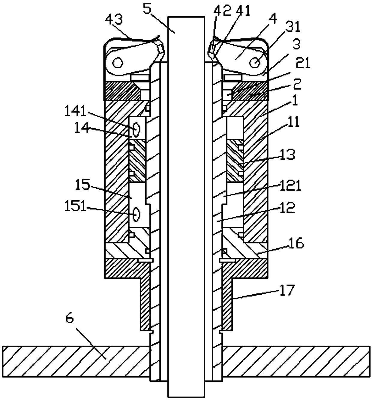
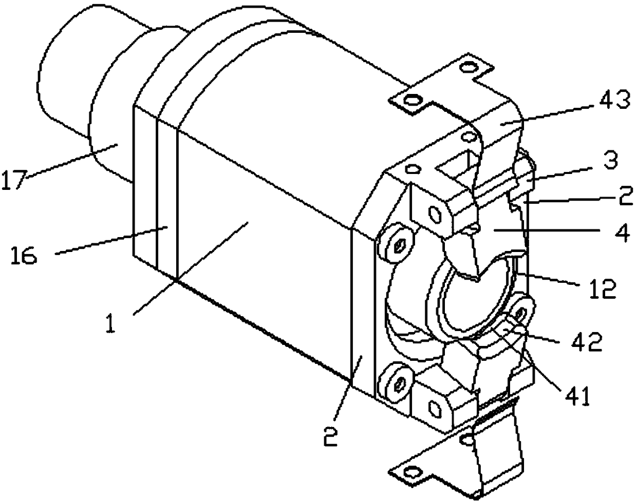
[0019] see Figure 1-2 , a pneumatic clamping device with a lifting function, including a cylinder 1, a mounting plate 2, a mounting seat 3 and a lifting rod 5; the cylinder 1 is a double-acting cylinder, and the lower end of the piston rod 12 is fixed on the beam 6; The piston rod 12 of the cylinder 1 is provided with a through hole for the lifting rod 5 to move up and down, and the lower end of the lifting rod 5 passes through the beam 6 and is connected wit...


PUM


Abstract

The invention discloses a pneumatic clamping device with an elevating function. The device comprises a cylinder, a mounting board, mounting seats and an elevating rod. The cylinder is a double-actingcylinder. Additionally, the lower end of a piston rod is fixed on a crossbeam. A perforating hole allowing the elevating rod to move up and down is arranged in the piston rod of the cylinder. The lower end of the elevating rod penetrates through the crossbeam to be connected with a cut head. The upper end of the cylinder is equipped with the mounting board. The middle of the mounting board is provided with a through hole allowing the elevating rod to pass through. The two groups of mounting seats are symmetrically installed outside the upper end of the mounting board. Clamp blocks capable of turning over towards the inside are hinged onto the mounting seat through hinged shafts. The clamping movement of the elevating rod is achieved. Then, the elevating rod is drive to ascend at fixed height such that the cut head can move upward for certain distance after cloth material is pressed. Accordingly, a fixed-length gap exists between the cut head and cloth material. The cloth material is prevented from wrinkling or turning over during movement so that garment quality is improved.

Description

technical field [0001] The invention relates to the technical field of cutting beds, in particular to a pneumatic clamping device with lifting function. Background technique [0002] Automatic cutting bed mainly includes cutting table, beam, cutting head, vacuum suction device and control system, etc. The crossbeam is erected on the cutting table, driven by the transmission shaft to move in the x-axis direction of the tabletop, the cutting head is installed on the crossbeam, driven by the transmission shaft to move in the y-axis direction of the tabletop, the cutting head is equipped with a cutter, crossbeam and cutting The heads jointly drive the cutter to complete various curves or straight lines on the table. The control system controls the cutting position, shape and route, cutting speed, cutting tool conversion, grinding distance, beam and cutting head start, temporary and termination cutting and other processes. When cutting, the fabric needs to be laid flat on the c...

Claims


Application Information

Patent Timeline
IPC IPC(8): D06H7/00
CPCD06H7/00
Inventor 罗华
Owner HEFEI AORUI DIGITAL CONTROL SCI & TECH
Features
  • R&D
  • Intellectual Property
  • Life Sciences
  • Materials
  • Tech Scout
  • Unparalleled Data Quality
  • Higher Quality Content
  • 60% Fewer Hallucinations
Learn More