Inclined well wall support construction method and inclined well wall support system

A construction method and technology for inclined wells, which are used in wellbore lining, shaft equipment, earth-moving drilling, etc., can solve the problems of uneven surface, complicated construction process, and inability to give full play to the supporting effect of steel shed supports.

Inactive Publication Date: 2018-11-30
ANHUI UNIV OF SCI & TECH
View PDF5 Cites 3 Cited by
  • Summary
  • Abstract
  • Description
  • Claims
  • Application Information

AI Technical Summary

Problems solved by technology

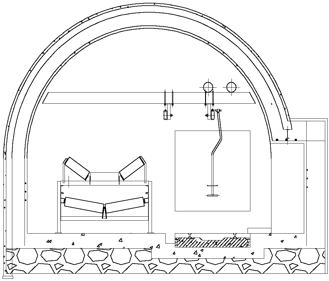
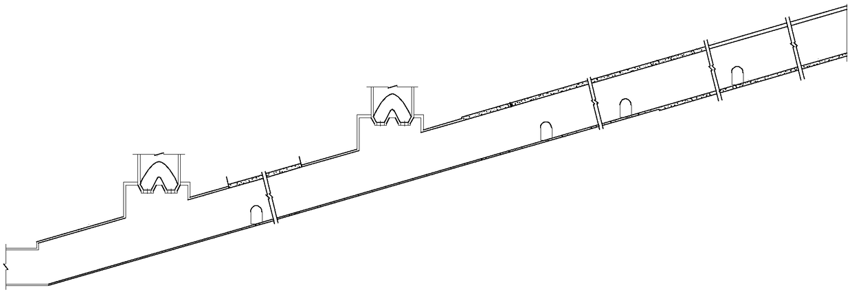
[0004] Inclined shaft support will be set in the inclined shaft. The original inclined shaft support structure mainly adopts "U-shaped steel shed support" + "reinforced concrete lining". In a certain range, the main inclined shaft is also sealed with masonry rubble mortar. Due to the limitation of space in the inclined shaft, the uneven surface of the inclined shaft wall, and the narrow gap between the inclined shaft wall and the steel shed support, the design of the shaft support structure will increase the difficulty of construction to a certain extent. The process is complicated, which seriously affects the overall construction progress of the main inclined shaft
In addition, due to the relatively complicated construction technology, there will be a large number of "point contact" structures between the reinforced concrete lining and the steel shed support, which will not only easily cause the local deformation of the steel shed support due to excessive force, but also fail to fully utilize it. Supporting effect of steel shed support

Method used


Image

  • Inclined well wall support construction method and inclined well wall support system
  • Inclined well wall support construction method and inclined well wall support system
  • Inclined well wall support construction method and inclined well wall support system

Examples


Embodiment Construction

[0033] The present invention will be described in detail below with reference to the accompanying drawings and examples. Each example is provided by way of explanation of the invention, not limitation of the invention. In fact, those skilled in the art will recognize that modifications and variations can be made in the present invention without departing from the scope or spirit of the invention. For example, features illustrated or described as part of one embodiment can be used on another embodiment to yield a still further embodiment. Therefore, it is intended that the present invention includes such modifications and variations as come within the scope of the appended claims and their equivalents.

[0034] In the description of the present invention, the terms "longitudinal", "transverse", "upper", "lower", "front", "rear", "left", "right", "vertical", "horizontal", " The orientations or positional relationships indicated by "top", "bottom", etc. are based on the orienta...


PUM


Abstract

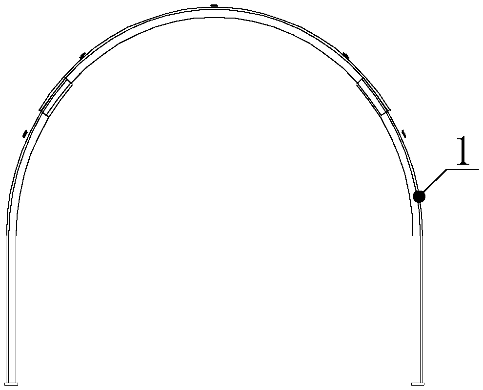
The invention provides an inclined well wall support construction method. The method comprises the steps that a steel support is firstly erected, crushed gangue is filled, a gangue layer is formed, asprayed concrete layer is formed by spraying concrete on the gangue layer, and a gap is filled. A set of inclined well wall support system is constructed by the inclined well wall support constructionmethod, the inclined well wall support system is based on a U-shaped steel shed support, a reinforcing bar mesh back plate is arranged on the steel support, the gangue is filled between the reinforcing mesh back plate and an inclined well wall, and a grout is filled in the gap between the gangue by grouting. The method adopts a wall back filler to uniformly transfer the external load from surrounding rocks to the steel support, so that the steel support receives a uniform load along the periphery, which is beneficial to exerting the supporting force of the steel support. The method reduces the rigidity of the filler, is very advantageous for reducing the surrounding rock pressure, adopts a method that the crushed gangue fills the rear space of the support to ensure the uniform bearing ofthe steel support, and reduces stress concentration points.

Description

technical field [0001] The invention relates to the technical field of underground roadway support, and more specifically relates to a construction method for shaft wall support of an inclined shaft and a shaft wall support system for an inclined shaft. Background technique [0002] Deviated well refers to a well with an inclined angle in drilling engineering. The wellhead and the design target point are not on the same vertical line, but deviate a certain distance from the vertical line of the wellhead in a given direction according to human needs. [0003] Please refer to figure 1 with figure 2 ,in, figure 1 It is a structural schematic diagram of the inclined shaft support system in the prior art; figure 2 It is a schematic diagram of the structure of the inclined well in the prior art. [0004] Inclined shaft support will be set in the inclined shaft. The original inclined shaft support structure mainly adopts "U-shaped steel shed support" + "reinforced concrete l...

Claims


Application Information

Patent Timeline
Patent Type & Authority Applications(China)
IPC IPC(8): E21D11/18E21F15/00E21D11/10E21F16/00
CPCE21D11/10E21D11/18E21F15/00E21F16/00
Inventor 程桦姚直书荣传新宋海清蔡海兵王晓健黎明镜
Owner ANHUI UNIV OF SCI & TECH
Why Eureka
Try Eureka