
Multi-mode spiral wave ion thruster

A technology of ion thruster and helical wave, which is applied in the direction of thrust reverser, plasma, machine/engine, etc., can solve the problem of excessive negative charge accumulation of the thruster, so as to avoid surface discharge phenomenon, prolong service life, and prevent The effect of gate corrosion

Inactive Publication Date: 2018-11-30
BEIJING INSTITUTE OF TECHNOLOGYGY
View PDF9 Cites 16 Cited by
  • Summary
  • Abstract
  • Description
  • Claims
  • Application Information

AI Technical Summary

Problems solved by technology

[0006] The purpose of the present invention is to solve the problem of excessive accumulation of thruster negative charge in the prior art, improve the ionization rate of the thruster, evaluate the performance of the thruster, and realize the multi-mode operation of the thruster, and provide a multi-mode helical wave ion thruster

Method used


Image

  • Multi-mode spiral wave ion thruster
  • Multi-mode spiral wave ion thruster

Examples


Embodiment 1

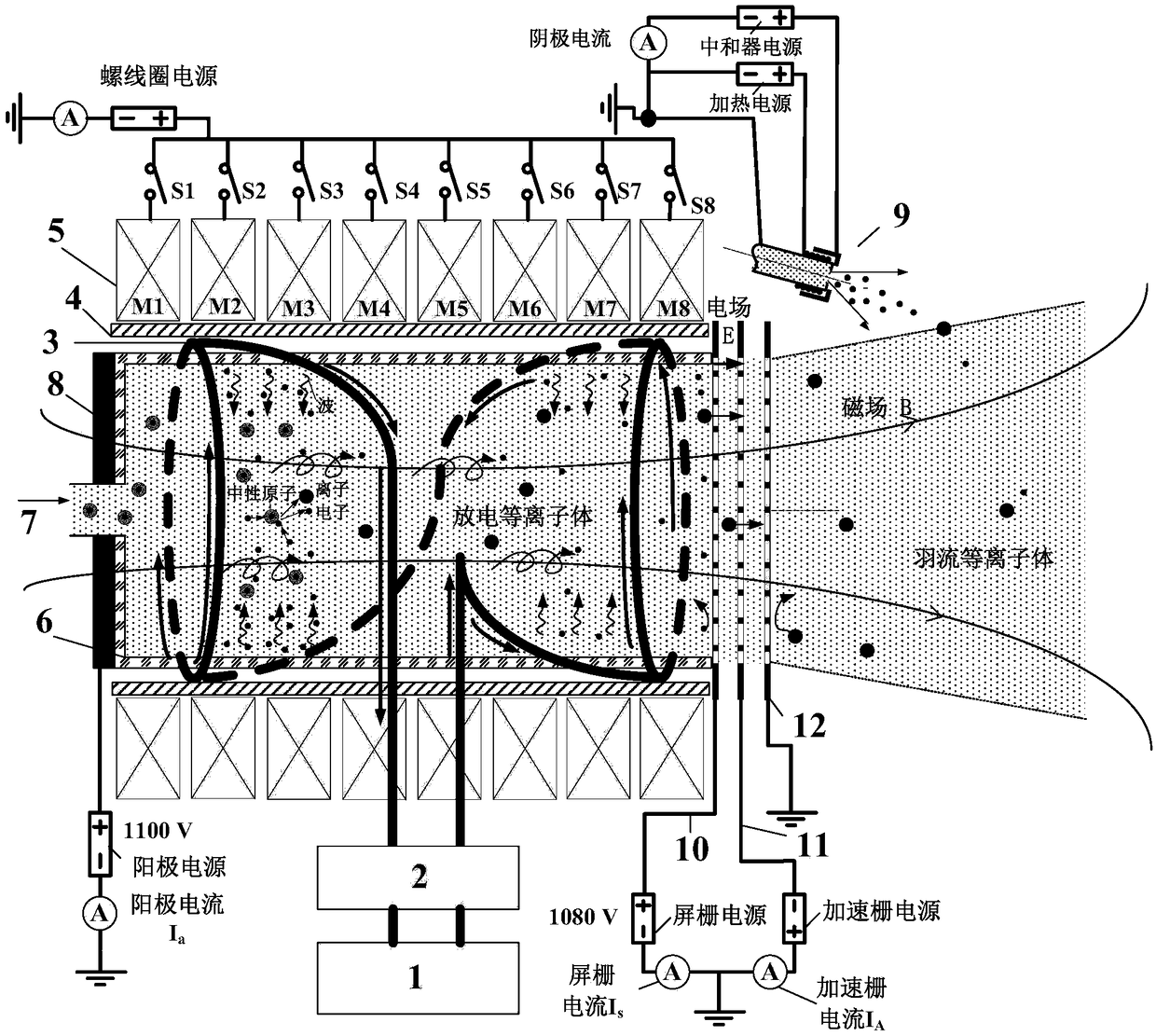
[0024] A multi-mode helicon wave ion thruster disclosed in this embodiment mainly consists of a radio frequency power source 1, a matcher 2, an antenna 3, a Faraday cylinder 4, a solenoid coil 5, a quartz discharge chamber 6, a propellant supply port 7, and an anode 8 , cathode neutralizer 9, screen grid 10, acceleration grid 11 and deceleration grid 12 and other helicon wave ion thruster basic device composition.

[0025] The radio frequency power source 1 generates radio frequency waves of a specific frequency, which are coupled into the plasma through the matching device 2 and the antenna 3 . The quartz discharge chamber 6 is placed in the Faraday cylinder 4; the quartz discharge chamber 6 is a semi-closed structure with an opening at one end; the anode 8 is fixed on the opening end of the quartz discharge chamber 6; the opening is the propellant supply port 7, the quartz The open end of the discharge chamber 6 is in contact with the screen grid 10; the screen grid 10, the ...


PUM


Abstract

The invention relates to a multi-mode spiral wave ion thruster and belongs to the field of aerospace electric propulsion. A quartz discharging chamber is placed in a Faraday barrel; an anode is fixedin an opening end of the quartz discharging chamber; an opening end of the quartz discharging chamber is in contact connection with a screen grid; the screen grid, an acceleration grid and a deceleration grid keep a distance; an antenna is mounted on an outer barrel wall of the quartz discharging chamber; a plurality of spiral coils are mounted on an outer wall of the Faraday barrel; a cathode neutralizer is placed at the opening end of the quartz discharging chamber and is used for neutralizing an electrostatic grid electrode to accelerate led-out ion beam flow; the cathode neutralizer and the anode generate an axial electric field, a route of electrons can be effectively increased and the ionization rate is improved. The thruster provided by the invention is provided with the neutralizerand the neutralizer can be used for neutralizing the ion beam flow led out from the electrostatic grid electrode; cathode and anode structures are arranged and the axial electric field can be provided, so that the ionization rate of plasmas is improved and the production cost of ions can be calculated; the designed spiral wave ion thruster has the advantages that an additional magnetic field hasan adjustable bit type and multi-mode working of the thruster can be realized.

Description

technical field [0001] The invention relates to a multi-mode helical wave ion thruster, in particular to a helical wave ion thruster with an adjustable additional magnetic field position type and a cathode neutralizer, an anode, and a three-grid electrostatic acceleration system, which belongs to aerospace electric propulsion field. Background technique [0002] The helicon wave ion thruster is a second-order accelerated helical wave thruster, which combines the advantages of high density, high ionization rate, and no electrodes of the helicon wave source, and the high-efficiency electrostatic acceleration of ions by the electrostatic grid optical system in the ion thruster. An electric propulsion device capable of generating high specific impulse and high thrust. [0003] Xia Guangqing of Dalian University of Technology proposed a double-stage grid helical wave ion propulsion device (CN201410597251.2), including a discharge chamber, a helical wave excitation antenna, a met...

Claims


Application Information

Patent Timeline
IPC IPC(8): F03H1/00
CPCF03H1/0068
Inventor 张尊欧阳吉庭谢侃王慧慧杨凯翼崔瑞林
Owner BEIJING INSTITUTE OF TECHNOLOGYGY
Learn More