
Fast neutron image detection device and manufacturing method of fast neutron detector array

A detector array and image detection technology, which is applied in scintillation detector measurement and other directions, can solve problems such as optical crosstalk, low detection efficiency, and low spatial resolution

Inactive Publication Date: 2018-11-30
LASER FUSION RES CENT CHINA ACAD OF ENG PHYSICS
View PDF4 Cites 6 Cited by
  • Summary
  • Abstract
  • Description
  • Claims
  • Application Information

AI Technical Summary

Problems solved by technology

The currently used scintillator units are mainly plastic scintillator optical fibers and glass capillary tubes filled with liquid scintillator. The researchers of this application found in the process of studying this application that it is difficult for the former to achieve a large aspect ratio (the ratio between the length and the cross-sectional size). Compared with) batch processing and high-precision, deformation-free assembly of scintillator units, the detection efficiency is low; and although the latter has realized batch processing, assembly and liquid scintillator filling of glass capillary tubes with a cross-sectional diameter of 50 microns and a length of 10 cm, But there is a serious optical crosstalk problem, which makes the spatial resolution low

Method used


Image

  • Fast neutron image detection device and manufacturing method of fast neutron detector array
  • Fast neutron image detection device and manufacturing method of fast neutron detector array
  • Fast neutron image detection device and manufacturing method of fast neutron detector array

Examples


Embodiment Construction

[0023] In order to make the purpose, technical solutions and advantages of the embodiments of the present invention clearer, the technical solutions in the embodiments of the present invention will be clearly and completely described below in conjunction with the drawings in the embodiments of the present invention. Obviously, the described embodiments It is a part of embodiments of the present invention, but not all embodiments. The components of the embodiments of the invention generally described and illustrated in the figures herein may be arranged and designed in a variety of different configurations.

[0024] Accordingly, the following detailed description of the embodiments of the invention provided in the accompanying drawings is not intended to limit the scope of the claimed invention, but merely represents selected embodiments of the invention. Based on the embodiments of the present invention, all other embodiments obtained by persons of ordinary skill in the art wi...


PUM

PropertyMeasurementUnit
Lengthaaaaaaaaaa
The inside diameter ofaaaaaaaaaa
Thicknessaaaaaaaaaa

Abstract

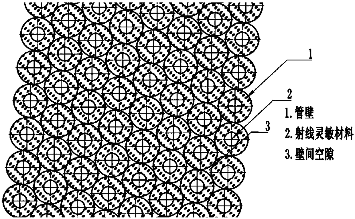
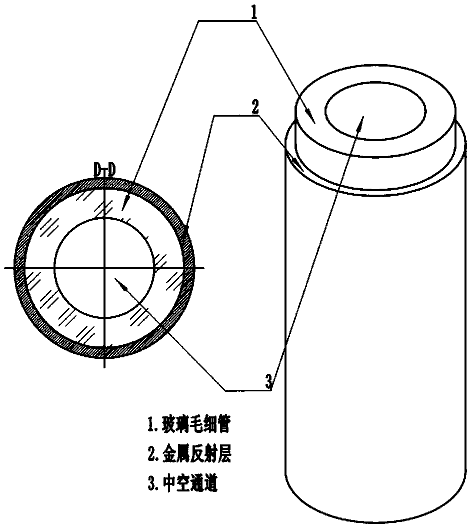
The invention relates to a fast neutron image detection device and a manufacturing method of a fast neutron detector array, and belongs to the technical field of fast neutron detection. The fast neutron image detection device comprises the fast neutron detector array which is constituted by a plurality of glass capillaries; the outer wall of each glass capillary is plated with a reflective film, and thus light is constrained in the current glass capillary and only transmitted to the two ends of the current glass capillary; and each glass capillary is filled with a ray sensitive material, thusfast neutrons and light nucleus in the ray sensitive materials generate elastic scattering, recoil charged nucleus enable organic molecules pi to be subjected to electron excitation on a flight path,the ground state is jumped into the excitation state, and glowing is conducted in a de-excitation mode. The outer wall of each glass capillary is plated with the reflective film, reflective layers exist, thus the visible light generated in each glass capillary is almost entirely transmitted to the two end faces of the glass capillary, and the problem of crosstalk of the light between the glass capillaries is avoided accordingly.

Description

technical field [0001] The invention belongs to the technical field of fast neutron detection, and in particular relates to a fast neutron image detection device and a method for manufacturing a fast neutron detector array. Background technique [0002] Fast neutron detection usually uses an organic scintillator, and its detection principle is: fast neutrons elastically scatter with abundant light nuclei (mainly protons, deuterium and carbon) in the organic scintillator, and recoil charged nuclei use Organic molecules are excited by π electrons, transition from the ground state to the excited state, the excited state is de-excited through the process of fluorescence and phosphorescence, and emits light, and then completes signal recording through light collection, photoelectric conversion, signal amplification, and acquisition systems to realize fast neutron detection . [0003] For fast neutron image detection, scintillator array detectors are usually selected, among which...

Claims


Application Information

Patent Timeline
IPC IPC(8): G01T3/06
CPCG01T3/06
Inventor 陈忠靖张兴晏骥蒋炜余波涂绍勇尹传盛蒲昱东董云松刘慎业
Owner LASER FUSION RES CENT CHINA ACAD OF ENG PHYSICS
Learn More