Supercharge Your Innovation With Domain-Expert AI Agents!

New energy vehicle battery installation structure

A new energy vehicle and installation structure technology, which is applied to secondary batteries, structural parts, electric power devices, etc., can solve the problem that the buffer function of the battery installation structure is not comprehensive enough, it is inconvenient for the battery to work normally for a long time, and the heat dissipation function of the installation structure is not good enough. and other problems, to achieve the effect of facilitating long-term normal work, improving installation convenience, and good buffering effect

Inactive Publication Date: 2018-11-30
韩智强
View PDF7 Cites 4 Cited by
  • Summary
  • Abstract
  • Description
  • Claims
  • Application Information

AI Technical Summary

Problems solved by technology

[0003] In the prior art, the heat dissipation function of the existing new energy vehicle battery installation structure is not good enough, the installation is not convenient enough, the heat generated by the battery is not easy to dissipate during the operation of the vehicle, and it is inconvenient for the battery to work normally for a long time. The existing new energy vehicle battery installation structure The buffering function is not comprehensive enough. The vibration generated during the operation of the car will easily cause the battery to follow the vibration and affect the service life of the battery. Now there is an urgent need for a new energy vehicle battery installation structure to solve the above problems.

Method used


Image

  • New energy vehicle battery installation structure
  • New energy vehicle battery installation structure
  • New energy vehicle battery installation structure

Examples


Embodiment Construction

[0020] In order to make the technical means, creative features, goals and effects achieved by the present invention easy to understand, the present invention will be further described below in conjunction with specific embodiments.

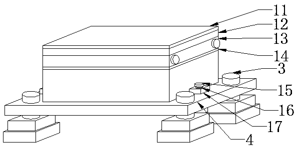
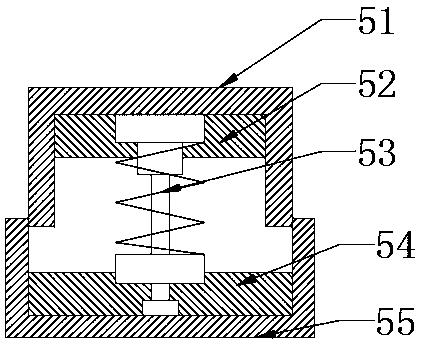
[0021] see Figure 1-Figure 3 , the present invention provides a technical solution: a new energy vehicle battery installation structure, including a convenient installation mechanism 1, a battery main body 2, a fixing column 3, a loading plate 4 and a buffer mechanism 5, and the battery main body 2 is installed on the loading plate 4 On the upper end surface, the convenient installation mechanism 1 is arranged outside the battery body 2 , the fixing column 3 is installed on the upper end surface of the loading plate 4 , and the buffer mechanism 5 is arranged on the lower side of the loading plate 4 .

[0022] The convenient installation mechanism 1 includes a thermal insulation pad 11, an extruded board 12, a plate heat exchanger 13, a thermally ...


PUM


Abstract

The invention provides a new energy vehicle battery installation structure, which comprises a plate type heat exchanger, a thermal conduction silica gel sheet, a long bolt, a positioning block, a weight bearing seat, a first magnet, a nylon vibration absorber, a second magnet and a fixing seat, wherein the thermal conduction silica gel sheet is arranged on the upper end surface of a battery main body, the plate type heat exchanger is arranged on the upper end surface of the thermal conduction silica gel sheet, the positioning block is fixed on the right end surface of the battery main body, and the long bolt is installed inside the positioning block. With the design of the present invention, the problems that the heat dissipation function of the original new energy vehicle battery installation structure is not good and the installation is not convenient are solved. According to the present invention, the weight bearing seat is installed on the lower end surface of the fixing column, the nylon vibration absorber is arranged inside the weight bearing seat, the first magnet is arranged on the upper side inside the weight bearing seat, and the second magnet is arranged on the lower side inside the fixing seat; with the design scheme of the present invention, the problem that the buffer function of the original new energy vehicle battery installation structure is not complete is solved; and the new energy vehicle battery installation structure has characteristics of reasonable structure, good buffering effect and convenient installation.

Description

technical field [0001] The invention relates to a new energy vehicle battery installation structure, which belongs to the technical field of new energy vehicle batteries. Background technique [0002] New energy vehicles refer to all other energy vehicles except gasoline and diesel engines, and their exhaust emissions are relatively low. The power battery box of the new energy vehicle is an important part of the new energy vehicle. The battery assembly is arranged in the battery box, the battery assembly is fixed on the bracket, and then fixed in the battery box through the bracket. [0003] In the prior art, the heat dissipation function of the existing new energy vehicle battery installation structure is not good enough, the installation is not convenient enough, the heat generated by the battery is not easy to dissipate during the operation of the vehicle, and it is inconvenient for the battery to work normally for a long time. The existing new energy vehicle battery inst...

Claims


Application Information

Patent Timeline
IPC IPC(8): H01M2/10H01M10/613H01M10/625H01M10/653H01M10/6554H01M10/6556H01M10/6567B60K1/04
CPCB60K1/04H01M10/613H01M10/625H01M10/653H01M10/6554H01M10/6556H01M10/6567H01M50/20Y02E60/10
Inventor 韩智强
Owner 韩智强
Features
  • R&D
  • Intellectual Property
  • Life Sciences
  • Materials
  • Tech Scout
  • Unparalleled Data Quality
  • Higher Quality Content
  • 60% Fewer Hallucinations
Learn More