Eureka AIR delivers breakthrough ideas for toughest innovation challenges, trusted by R&D personnel around the world.

Heat treatment process for parts for automobile shock absorption system and heat treatment support frame

A technology of automobile shock absorption and shock absorption system, which is applied in heat treatment furnaces, heat treatment equipment, manufacturing tools, etc., can solve the problems of uniform distribution of unfavorable heat conduction, damage to the integrity of materials, and disorderly placement, and achieve improved mechanical strength and hardness. Improve the metallographic structure and promote the effect of heat flow up and down

Inactive Publication Date: 2018-12-04
ANHUI LUOSHI SHENGTAI AUTO PARTS
View PDF3 Cites 1 Cited by
  • Summary
  • Abstract
  • Description
  • Claims
  • Application Information

AI Technical Summary

Problems solved by technology

Most of the currently used supporting frames are cylindrical supporting frames, such as the patent of CN 207418812 U. Although the bottom of the supporting frame for heat treatment is a hollow structure, the heat dissipation effect is better and the bottom will not accumulate oil, but The materials are all piled up together, and the placement is messy and will damage the integrity of the materials to a certain extent. At the same time, the accumulation is not conducive to the uniform distribution of heat conduction, so it is not an ideal heat treatment support frame

Method used


Image

  • Heat treatment process for parts for automobile shock absorption system and heat treatment support frame
  • Heat treatment process for parts for automobile shock absorption system and heat treatment support frame
  • Heat treatment process for parts for automobile shock absorption system and heat treatment support frame

Examples


Embodiment Construction

[0017] Specific embodiments of the present invention will be described in detail below. It should be understood that the specific embodiments described here are only used to illustrate and explain the present invention, and are not limited to these examples.

[0018] A heat treatment process for parts used in an automobile shock absorbing system, the heat treatment process comprising:

[0019] (1) Solid solution: Heat the parts used for the shock absorber system to 525-535°C, keep them warm for 90 minutes, then quench the parts for 5-6 minutes (water temperature 15-50 degrees Celsius), take them out and cool them naturally for 6-48 hours, then carry out artificial aging ;

[0020] (2) Artificial aging: Heat the components of the shock absorbing system to 165-185°C, keep them warm for 10 hours, take them out and cool them down to room temperature naturally.

[0021] The above-mentioned heat treatment support frame for the heat treatment of parts of the automobile shock absorp...


PUM


Abstract

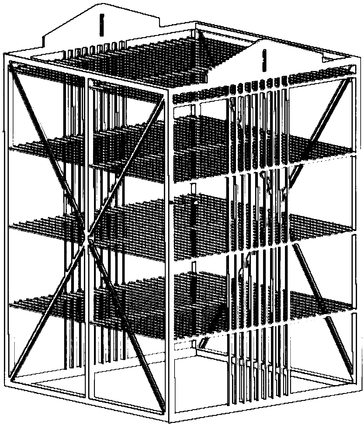
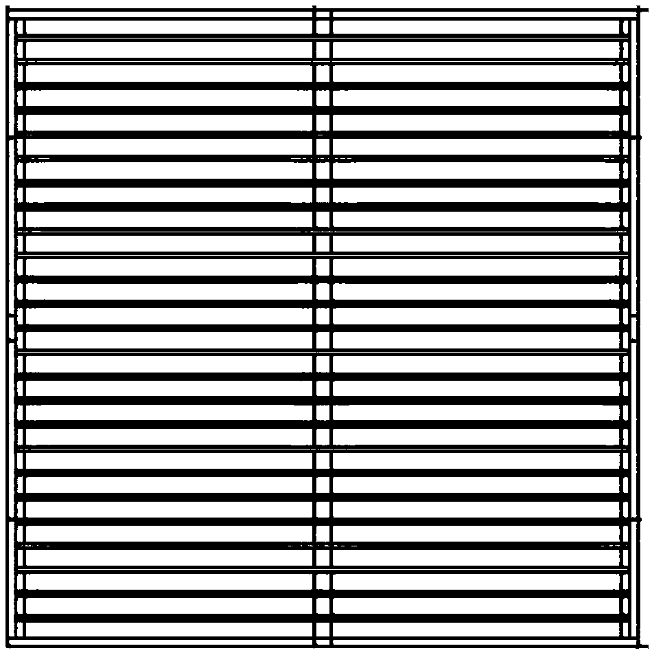
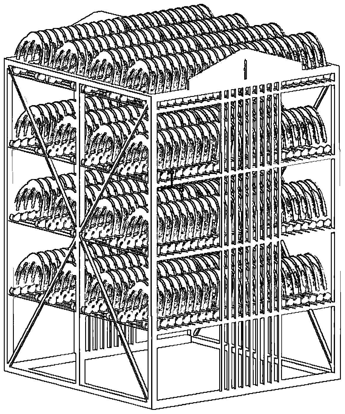
The invention discloses a heat treatment process for parts for an automobile shock absorption system and a heat treatment support frame, the heat treatment process comprises normalizing treatment, quenching treatment and tempering treatment; and the parts are placed in a heat treatment furnace for heat treatment by the heat treatment support frame. The heat treatment support frame comprises a frame body, the frame body is composed of a top square frame, intermediate layer square frames, a bottom square frame and a plurality of side frame pillars, the plurality of side frame pillars are vertically welded to the top corners of the top square frame and the bottom square frame, the intermediate layer square frames are sequentially in parallel ate intervals welded to the side frame pillars connecting the top square and the bottom square frame, and strip-like grilling are welded on the intermediate layer square frames. The heat treatment support frame is more reasonable in structure comparedwith that in the prior art, the parts can be placed neatly, the accommodation space is large without damaging the integrity of the parts, the heat conduction is more uniform, the heat treatment efficiency is improved; and the heat treatment process improves the mechanical strength and hardness of the parts, and improves metallographic structures.

Description

technical field [0001] The invention belongs to the field of heat treatment and heat treatment equipment, and in particular relates to a heat treatment process for parts used in an automobile shock absorbing system and a heat treatment support frame. Background technique [0002] Heat treatment refers to a metal thermal processing process in which the chemical composition and structure of the surface or interior of the material are changed by means of heating, heat preservation and cooling in the solid state to obtain the required properties. During the heat treatment process, multiple materials need to be placed in the support frame, and the materials complete the heat treatment process by moving the support frame. Most of the currently used supporting frames are cylindrical supporting frames, such as the patent of CN 207418812 U. Although the bottom of the supporting frame for heat treatment is a hollow structure, the heat dissipation effect is better and the bottom will n...

Claims


Application Information

Patent Timeline
Patent Type & Authority Applications(China)
IPC IPC(8): C21D1/00C21D1/18C21D9/00
CPCC21D1/00C21D1/18C21D9/0068
Inventor 潘阿城杨寿艮杨建王清沈启飞吴松花洪翠萍陈青青
Owner ANHUI LUOSHI SHENGTAI AUTO PARTS
Why Eureka
Eureka Blog
Learn More