
Air conditioning system

A technology of air conditioning system and circulation system, applied in the field of air conditioning, can solve problems such as inconvenient installation and inability to install outdoor units, and achieve the effects of reducing wiring, improving annual energy efficiency ratio, and improving work reliability

Inactive Publication Date: 2018-12-04
EMERSON NETWORK POWER CO LTD
View PDF5 Cites 0 Cited by
  • Summary
  • Abstract
  • Description
  • Claims
  • Application Information

AI Technical Summary

Problems solved by technology

[0007] The purpose of the embodiments of the present invention is to provide an air conditioning system to overcome the problems in the prior art that the outdoor unit cannot be installed or the installation is inconvenient due to the outdoor on-site installation environment, reduce the outdoor floor area, reduce the cost, and improve the annual energy efficiency ratio , improve system reliability

Method used


Image

  • Air conditioning system
  • Air conditioning system
  • Air conditioning system

Examples


Embodiment 1

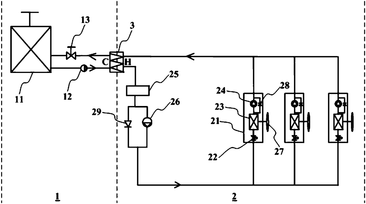
[0051] Such as figure 1 As shown, the air conditioning system provided by the first embodiment of the present invention includes an intermediate heat exchanger 3, a first refrigeration unit 1 and a second refrigeration unit 2, wherein:

[0052] The first refrigerating unit 1 includes a cooling water circulation system, and the cooling water circulation system includes an outdoor cooling tower 11, a first liquid pump 12, and the cold side of an intermediate heat exchanger 3 connected in sequence (letter C represents the intermediate heat exchange in the accompanying drawings of each embodiment. The cold side of the device 3, the letter H represents the hot side of the intermediate heat exchanger 3) and the first flow control valve 13;

[0053] The second refrigerating part 2 includes a compressor circulation system and a pump circulation system and includes at least two indoor refrigeration terminals 21 arranged in parallel. The compressor circulation system includes the hot si...

Embodiment 2

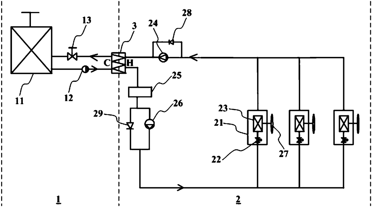
[0063] Such as figure 2 As shown, based on the same inventive concept as in Embodiment 1, in the air-conditioning system provided in Embodiment 2 of the present invention, in the indoor refrigeration terminal 21, the evaporator located in the compressor circulation system and the evaporator located in the pump circulation system are the same evaporator 23 The compressor 24 is independent of each indoor cooling terminal 21, and the indoor cooling terminal 21 also includes a fan 27 opposite to the evaporator 23. The hot side of the intermediate heat exchanger 3, the liquid storage tank 25, the second liquid pump 26, the second flow control valve 22, the evaporator 23 and the compressor 24 are sequentially connected as a closed-loop circuit; 24 in parallel with the first one-way valve 28, and the second one-way valve 29 in parallel with the second liquid pump 26.

[0064] In this embodiment, the compressor 24 and the first one-way valve 28 are independent from the indoor coolin...

Embodiment 3

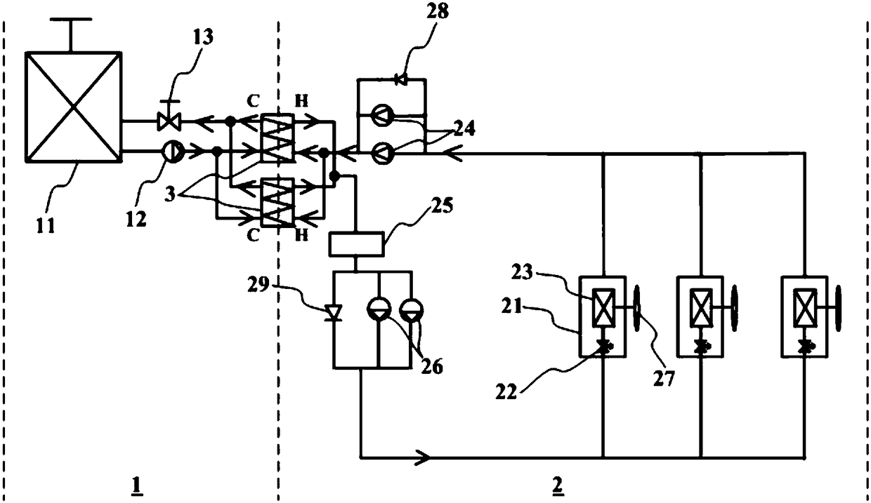
[0066] Such as image 3 As shown, on the basis of Embodiment 2, in the air conditioning system provided by Embodiment 3 of the present invention, there are at least two compressors 24 arranged in parallel, at least two second liquid pumps 26 arranged in parallel, and the intermediate heat exchanger 3 are at least two, and the cold sides of the at least two intermediate heat exchangers 3 are arranged in parallel, and the hot sides of the at least two intermediate heat exchangers 3 are arranged in parallel.

[0067] When one of the compressors 24 breaks down, any other compressor connected in parallel with it can continue to work, thereby increasing the reliability of the air-conditioning system. Especially in summer, related losses due to compressor failure can be greatly reduced. Similarly, at least two second liquid pumps 26 and the intermediate heat exchanger 3 are provided to increase the reliability of the air-conditioning system.


PUM


Abstract

The invention discloses an air conditioning system used for solving the problem that an outdoor unit cannot be installed or is inconvenient to install in the prior art, and the air conditioning systemcan reduce the outdoor occupied area, lower the cost and improve the energy efficiency ratio of the whole year and the working reliability. The air conditioning system comprises an intermediate heatexchanger, a first refrigerating part and a second refrigerating part, wherein the first refrigerating part comprises a cooling water circulating system, and the cooling water circulating system comprises an outdoor cooling tower, a first liquid pump, a cold side of the intermediate heat exchanger and a first flow control valve which are connected in sequence; the second refrigerating part comprises a compressor circulating system, a pump circulating system and at least two indoor refrigerating tail ends arranged in parallel, the compressor circulating system comprises a heat side of the intermediate heat exchanger, a second flow control valve, an evaporator and a compressor which are sequentially connected, and the pump circulating system comprises the heat side of the intermediate heat exchanger, a liquid storage tank, a second liquid pump and an evaporator which are sequentially connected; and each indoor refrigerating tail end comprises the second flow control valve and the evaporator of the compressor circulating system and the evaporator of the pump circulating system.

Description

technical field [0001] The invention relates to the technical field of air conditioning, in particular to an air conditioning system. Background technique [0002] With the development of modern information technology, the number and scale of communication equipment rooms across the country are also expanding. Under the call of the national energy conservation and emission reduction policy, reducing energy consumption in computer rooms has become the focus of many operators. According to the survey, in the computer room, the power consumption of the precision air conditioner alone accounts for more than 50% of the total electricity consumption of the computer room. In a large number of base stations and module bureaus, the power consumption of air conditioners can reach about 70% of the total power consumption of the base stations or module bureaus. Therefore, effectively reducing the power consumption of air conditioners has become an important direction to reduce the ene...

Claims


Application Information

Patent Timeline
IPC IPC(8): F24F5/00F24F13/30
CPCF24F5/001F24F13/30
Inventor 万积清马丽强谯峤梁婷位静
Owner EMERSON NETWORK POWER CO LTD
Features
  • Generate Ideas
  • Intellectual Property
  • Life Sciences
  • Materials
  • Tech Scout
  • Unparalleled Data Quality
  • Higher Quality Content
  • 60% Fewer Hallucinations
Learn More