High magnetic field strength, high uniformity nuclear magnetic resonance magnet structure and measuring device

A technology of magnetic field strength and nuclear magnetic resonance, which is applied in the direction of magnetic resonance measurement, measuring devices, magnets, etc., can solve problems such as the inability to meet the requirements of magnetic field uniformity, the limitation of the working range of the detection device, and the small detection signal strength, etc., to increase the magnetic field Uniform area body, increase the volume of the uniform area of ​​the magnetic field, and the effect of large volume of the uniform area

Active Publication Date: 2020-06-09
CHINA UNIV OF PETROLEUM (BEIJING)
View PDF5 Cites 0 Cited by
  • Summary
  • Abstract
  • Description
  • Claims
  • Application Information

AI Technical Summary

Problems solved by technology

However, with the development of nuclear magnetic resonance detection technology, people have higher and higher requirements for the accuracy of the detection results, which in turn requires the magnet of the nuclear magnetic resonance detector to be able to generate a magnetic field with higher uniformity, such as figure 2 The structure of the magnet shown can no longer meet people's requirements for the uniformity of the magnetic field
and if figure 2 In the shown NMR detector magnet, the magnetic field generated by it is evenly distributed in the horizontal direction and the magnetic field strength is low, which directly leads to the low strength of the detection signal and low signal-to-noise ratio, which in turn leads to a small detection distance, such as If the magnetic field strength needs to be increased, the volume of the magnet needs to be greatly increased, which not only increases the production cost, but also limits the scope of application of the detection device.

Method used


Image

  • High magnetic field strength, high uniformity nuclear magnetic resonance magnet structure and measuring device
  • High magnetic field strength, high uniformity nuclear magnetic resonance magnet structure and measuring device
  • High magnetic field strength, high uniformity nuclear magnetic resonance magnet structure and measuring device

Examples


Embodiment Construction

[0027] In order to make the purpose, technical solutions and advantages of the embodiments of the present invention clearer, the technical solutions in the embodiments of the present invention will be clearly and completely described below in conjunction with the drawings in the embodiments of the present invention. Obviously, the described embodiments It is a part of embodiments of the present invention, but not all embodiments. Based on the embodiments of the present invention, all other embodiments obtained by those skilled in the art without creative efforts fall within the protection scope of the present invention.

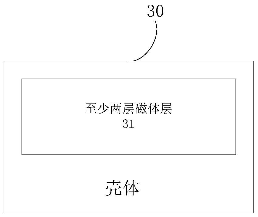
[0028] image 3 It is a schematic diagram of a high magnetic field intensity and high uniformity nuclear magnetic resonance magnet structure shown in an exemplary embodiment of the present invention.

[0029] Such as image 3 As shown, this embodiment provides a high magnetic field strength, high uniformity nuclear magnetic resonance magnet structure, the m...


PUM


Abstract

The invention provides a high-magnetic-field-strength and high-uniformity nuclear magnetic resonance magnet structure and a measuring device. The magnet structure comprises a housing and at least twomagnet layers which are arranged in the housing, wherein at least two magnet layers are vertically stacked in the housing. The magnetization directions of at least two magnet layers are same. According to the invention, through vertically stacking two or more magnet layers with the same magnetization directions in the housing, the nuclear magnetic resonance magnet structure is formed. The magneticfields which are generated by two or more magnet layers are stacked, thereby generating a static magnetic field together. Compared with a static magnetic field which is generated by a single layer ofmagnet, the static magnetic according to the invention has advantages of improving magnetic field uniformity and magnetic field strength, and increasing the area of a uniform area and detecting distance. Through cooperative use of a specific RF antenna and the magnet structure, layered heterogeneous samples and homogeneous samples can be effectively measured, thereby expanding application range of a nuclear magnetic resonance measurement device.

Description

technical field [0001] The invention relates to the technical field of nuclear magnetic resonance, in particular to a high magnetic field strength and high uniformity nuclear magnetic resonance magnet structure and a measuring device. Background technique [0002] Nuclear Magnetic Resonance (NMR) is a new analytical technique developed in the 1940s. The use of NMR technology can determine the chemical structure of a substance and the density distribution of a certain component without destroying the sample. Its application has rapidly expanded to the fields of physics, chemistry, material science, life science and medicine. In the 1950s, nuclear magnetic resonance detection technology began to be applied in the oil and gas industry. Nuclear magnetic resonance detection technology is a technology that uses the principle of nuclear magnetic resonance to detect hydrogen atoms. By detecting the content and occurrence state of hydrogen atoms in the sample, the information of va...

Claims


Application Information

Patent Timeline
Patent Type & Authority Patents(China)
IPC IPC(8): G01R33/383G01R33/38H01F7/02
CPCG01R33/38G01R33/383H01F7/0284H01F7/0294
Inventor 肖立志孙哲廖广志李新罗嗣慧
Owner CHINA UNIV OF PETROLEUM (BEIJING)
Why Eureka
Try Eureka