Pulse modulator and drive circuit thereof

A pulse modulator and driving circuit technology, applied in pulse duration/width modulation, pulse technology, electrical components, etc., can solve the problem of inability to turn on the electronically controlled switch and turn off quickly, so as to reduce the consumption time and investment cost. , Improve the effect of circuit reliability

Active Publication Date: 2018-12-04
THE PLA INFORMATION ENG UNIV
View PDF8 Cites 1 Cited by
  • Summary
  • Abstract
  • Description
  • Claims
  • Application Information

AI Technical Summary

Problems solved by technology

[0006] The purpose of the present invention is to provide a pulse modulator to solve the problem

Method used


Image

  • Pulse modulator and drive circuit thereof
  • Pulse modulator and drive circuit thereof
  • Pulse modulator and drive circuit thereof

Examples


Example Embodiment

[0025] Pulse Modulator Embodiment

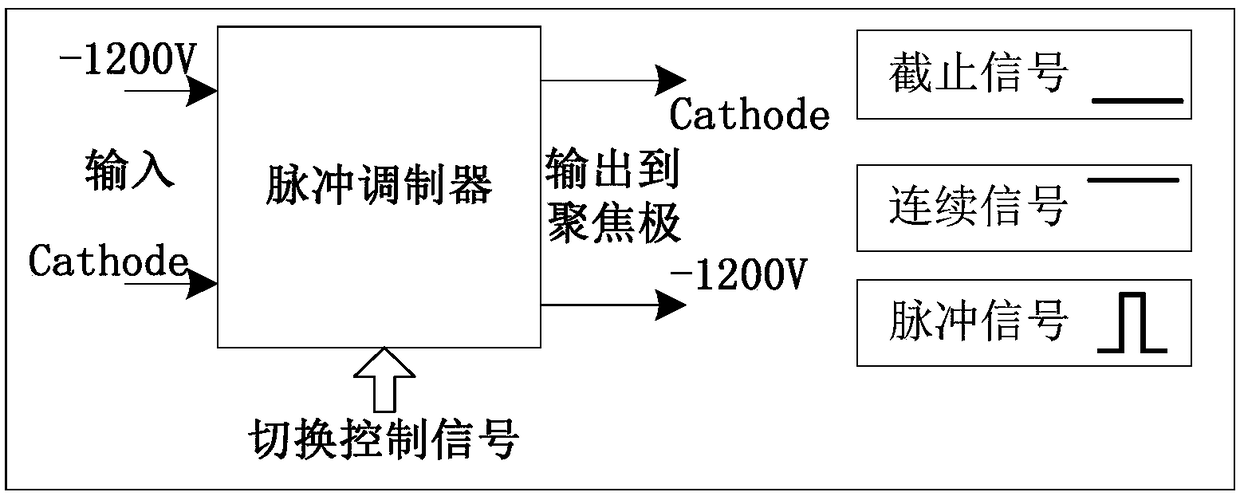
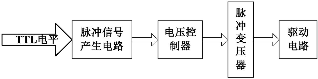
[0026] like figure 2 As shown, the basic components of the pulse modulator include a pulse signal generating circuit, a voltage controller, a pulse transformer and a driving circuit. The pulse signal generation circuit is used to generate the corresponding pulse signal according to the input control signal and transmit it to the voltage controller. The voltage controller is used to enhance the driving ability of the pulse signal sent by the pulse signal generation circuit, and then isolated and transmitted through the pulse transformer. The driving circuit is controlled, and the traveling wave tube is driven by the driving circuit.

[0027] The driving circuit is provided with an opening electric control switch and a tail chopping electric control switch. Both the opening electric control switch and the tail chopping electric control switch are electric control type control switches. The control switch is a cut tail tube, and both the ope...


PUM


Abstract

The invention relates to a pulse modulator and a drive circuit thereof. The drive circuit comprises a start electric control switch and a censored electric control switch, the start electric control switch and the censored electric control switch are arranged in series, a discharge branch is further arranged in the drive circuit, the discharge branch is connected to a control end of the start electric control switch, a discharge electric control switch is arranged in series on the discharge branch, and a control end of the discharge electric control switch is connected to a censored pulse generation unit. When the censored pulse generation unit outputs a drive signal, a start pulse generation unit stops outputting the drive signal, the discharging electric control switch is turned on by the drive signal, and a parasitic capacitor on the start electric control switch is turned on to discharge through the discharge branch so that a level keeping the start electric control switch to be turned on quickly becomes a low level, the start electronic control switch is turned off quickly then. Compared with a traditional drive circuit that only a drive signal is stop outputting, the drive circuit is advantageous in that time consumed by cut-off of the start electric control switch is greatly reduced, and fast cut-off of the start electric control switch is achieved.

Description

technical field [0001] The present invention relates to a pulse modulator and its driving circuit. Background technique [0002] The pulse modulator is an indispensable and important part of the pulse radar transmitter. It can generate pulse signals with adjustable pulse width and repetition frequency to control the operation of the traveling wave tube. Generally, the working state of the traveling wave tube can be divided into three types: pulse, continuous and cut-off. [0003] Since the stability, noise and spectral characteristics of the radar system are directly related to the pulse modulator's leading and trailing edge time, time jitter, pulse top waveform, top landing and pulse stability of the modulated pulse, modern pulse transmitters are not sensitive to pulse stability. Modulator waveforms impose extremely stringent requirements. Both the small size of the pulse transformer and the high reliability are required, and various performance indicators must be optimiz...

Claims


Application Information

Patent Timeline
IPC IPC(8): H03K7/08H03K17/04
CPCH03K7/08H03K17/04
Inventor 李建兵周东方仝博宾王妍舒君朱明俊姜海洋
Owner THE PLA INFORMATION ENG UNIV
Why Eureka
Try Eureka