Multi-task driving and dimming light emitting module and method

A light-emitting module and multi-tasking technology, applied in the direction of electroluminescent light source, light source, electric light source, etc., can solve the problems affecting the circuit layout and complexity of the circuit board, occupying a volume that makes the overall space use, and brightness control complicated.

Inactive Publication Date: 2018-12-04
CHICONY POWER TECHNOLOGY(SUZHOU) CO LTD
View PDF10 Cites 4 Cited by
  • Summary
  • Abstract
  • Description
  • Claims
  • Application Information

AI Technical Summary

Problems solved by technology

[0005] With the increasing performance requirements of the keyboard backlight display, the driving circuit for the LED is continuously developed, and it is gradually integrated into the integrated circuit and applied to the light-emitting module of the keyboard backlight display, and the keyboard can be controlled through the light-emitting module. The brightness of the backlight, the light-emitting module includes a plurality of LEDs and a control circuit, and the control circuit includes a power supply, a driver chip and a pulse width modulation generator, the driver chip is connected between the power supply and a plurality of LEDs, the pulse The wide modulation generator is connected between the power supply and the driver chip to generate a pulse width modulation signal, which can be used to control the driver chip to adjust the brightness of the LED, but the multiple LEDs of the light-emitting module correspond to the positions of the keycaps , and in the practical application of the keyboard, in order to provide the uniformity and stability of the LED current, and to respond quickly to the input voltage change, it is generally necessary to use four driver chips to provide four channels of current according to the pulse width modulation signal. Only by driving multiple LEDs can the brightness of the LEDs be adjusted to keep it stable, thereby improving the efficiency of the keyboard backlight. This kind of control circuit uses four driver chips, which will not only affect the circuit layout and complexity on the circuit board, but also occupy a certain amount of time. In addition to limiting the use of the overall space due to the volume, it will also increase the cost of manufacturing and installing multiple driver chips, and the brightness control of multiple LEDs by the multiple driver chips becomes complicated, and it also consumes a large amount of power in the control circuit. power, it needs to be redesigned by those engaged in this industry to be effectively improved

Method used


Image

  • Multi-task driving and dimming light emitting module and method
  • Multi-task driving and dimming light emitting module and method

Examples


Embodiment Construction

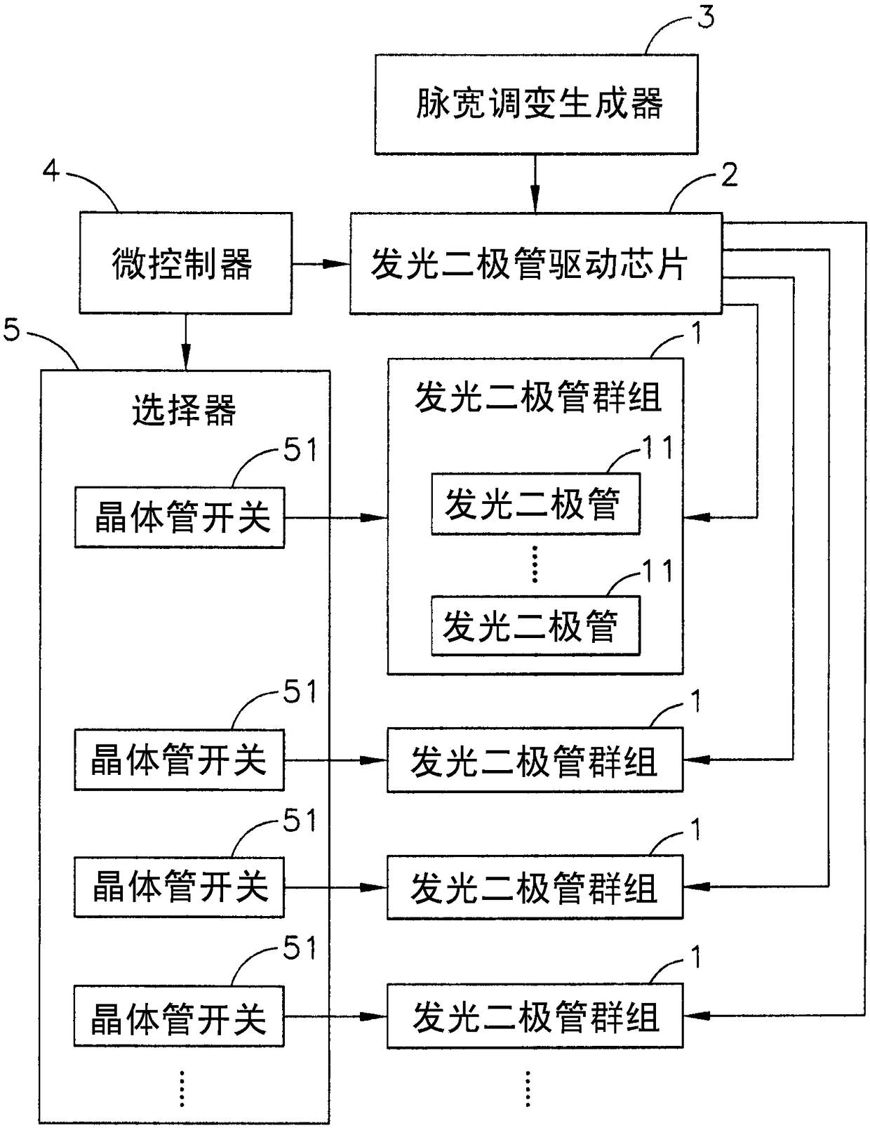
[0011] see figure 1 Shown is a block diagram of the multi-task drive control circuit of the light-emitting module of the present invention. It can be clearly seen from the figure that the multi-task drive dimming light-emitting module of the present invention includes a plurality of light-emitting diode groups 1, a light-emitting diode Driver chip 2, a pulse width modulation generator 3, a microcontroller 4 and a selector 5, wherein:

[0012] The light emitting diode group 1 includes six groups of four light emitting diodes 11 each connected in parallel and the number is twenty-four, and the multi-task driving control circuit of the light emitting module of the present invention has four light emitting diode groups in this embodiment 1. The four light-emitting diode groups 1 include twenty-four groups of light-emitting diodes 11 each having four parallel connections and a number of ninety-six light-emitting diodes. The number of light emitting diodes 11 can be appropriately c...


PUM


Abstract

The present invention provides a multi-task driving and dimming light emitting module and method, wherein a light emitting diode driving chip is electrically connected to the plurality of light emitting diode groups, a pulse width modulation generator and a microcontroller are electrically connected to the light emitting diode driving chip, a selector is electrically connected to the microcontroller and the plurality of light emitting diode groups, the plurality of light emitting diode groups can be respectively controlled in terms of luminance according to a pulse width modulation set value of a pulse width modulation generator via the light emitting diode driving chip, the light emitting diode driving chip is used for controlling the plurality of LED groups to orderly illuminate at different times according to a driving set value of the microcontroller in a frequency scanning manner, the selector controls the plurality of light emitting diode groups to form light-emitting frequenciesthat human eyes do not find flickering according to a control switching set value of the microcontroller, and an aim of realizing a multi-task driving and dimming function of a single light emittingdiode driving chip can be attained.

Description

technical field [0001] The present invention provides a light-emitting module and method for multi-task driving and dimming, in particular, it can use a microcontroller to control a light-emitting diode drive chip to output pulse width modulation set values ​​at different times in a frequency scanning manner, and a selector to Multiple light-emitting diode groups are controlled separately to form light-emitting frequencies that human eyes will not find flickering. Background technique [0002] The rapid development of today's electronic technology and information industry has led to the development of various electronic products towards the trend of light, thin, short, small and powerful functions, such as computers, notebook computers, mobile Internet devices (MID), smart phones, tablet computers etc., have become indispensable electronic products in the daily life or work of modern people, and most of the users and electronic products use mouse, keyboard and other input de...

Claims


Application Information

Patent Timeline
Patent Type & Authority Applications(China)
IPC IPC(8): H05B33/08H05B44/00
CPCH05B45/00Y02B20/30
Inventor 陈义文郑维浩
Owner CHICONY POWER TECHNOLOGY(SUZHOU) CO LTD
Why Eureka
Try Eureka