A kind of mag welding circumferential welding method
A technology of circumferential welding and welded joints, which is applied in the field of MAG welding circumferential welding, can solve the problems such as difficult connection of joints, difficulty in removal, and hidden dangers of weld quality, so as to prolong arc starting operation time, ensure structural uniformity, and good fusion Effect
- Summary
- Abstract
- Description
- Claims
- Application Information
AI Technical Summary
Problems solved by technology
Method used
Image
Examples
Embodiment 1
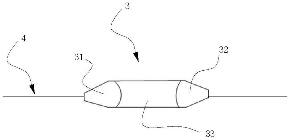
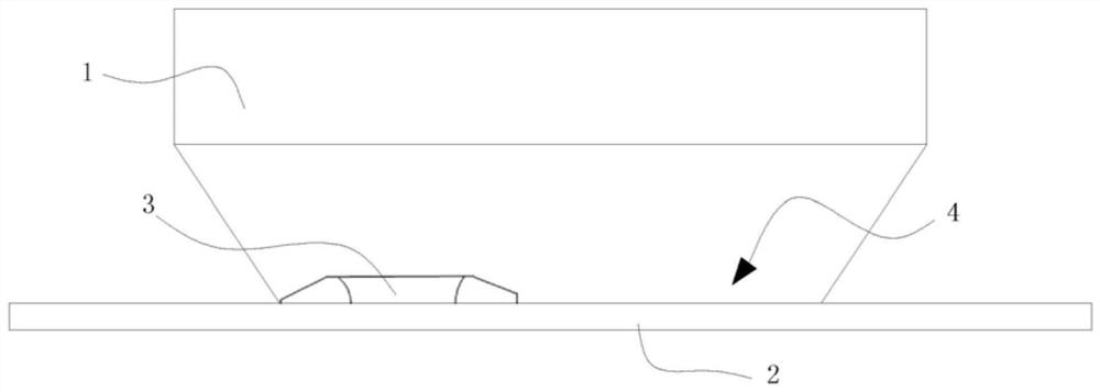
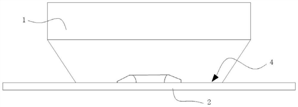
[0054] Such as Figure 1 to Figure 4 As shown, the MAG welding circumferential welding method described in this embodiment comprises the following steps:
[0055] S1. Determine the relative positions of the first piece 1 and the second piece 2 to be welded;
[0056] S2. Arranging arc start and stop weldment at welding joint 4;
[0057] S3. After the arc start and stop weldment is cooled to a certain temperature, the two ends are processed to form the start and stop welding section 3; the two ends of the start and stop welding section 3 are respectively the arc start end 31 and the arc stop end 32 ;
[0058] S4. Start the arc at the arc starting end 31, and move the welding torch along the circumferentially closed welding joint 4 to form a weld bead;
[0059] S5. When the formed weld bead reaches the arc-ending end 32, the arc is stopped at the arc-ending end. The profile of the welded joint is circular (annular). Preferably, the arc-starting end and the arc-ending end have ...
Embodiment 2
[0065] Such as Figure 1 to Figure 4 As shown, the difference between the MAG welding circumferential welding method described in this embodiment and the above-mentioned embodiments is that in the welding operation in this embodiment, before implementing step S4, heat treatment is performed on the arc starting end 31, so that the arc starting end 31 When the temperature rises to a certain level, the operation of forming the weld bead can increase the wettability between the starting point of the weld bead and the arc starting end, and avoid the formation of defects between the two.
[0066] Further, in the welding operation in this embodiment, when the welding bead is formed, the torch is evenly moved until the trajectory of the welding bead covers the circumference of the welding joint position, and then the welding torch is closed at the arc-ending end 32 to form a complete circular contour .
[0067] Further, the welding operation step S5 in this embodiment also includes s...
Embodiment 3
[0071] Such as Figure 1 to Figure 4 As shown, the difference between the MAG welding circumferential welding method described in this embodiment and the above-mentioned embodiment is that: after the step S5, it also includes steps:
[0072] S7. Perform end treatment on the end formed by the arc closing operation in step S5, and use it as the arc starting end, repeat steps S4 to S6 to form at least two welding passes until the welding operation is completed; preferably, the end Methods of internal treatment include sanding.
[0073] In the welding operation method in this embodiment, the ends of the arc start and end welding section 3 are processed, so that the arc start point and the arc end point between the end and the weld bead can be well transitioned, and the microscopic structure can be guaranteed. Uniformity can also ensure macroscopic structural uniformity, reducing or even avoiding subsequent surface treatment operations.
[0074] Further, the end processing in thi...
PUM
 Abstract
Description
Claims
Application Information
 - R&D
- Intellectual Property
- Life Sciences
- Materials
- Tech Scout
- Unparalleled Data Quality
- Higher Quality Content
- 60% Fewer Hallucinations
Browse by: Latest US Patents, China's latest patents, Technical Efficacy Thesaurus, Application Domain, Technology Topic, Popular Technical Reports.
© 2025 PatSnap. All rights reserved.Legal|Privacy policy|Modern Slavery Act Transparency Statement|Sitemap|About US| Contact US: help@patsnap.com


