
New energy electric vehicle safety charging device

A technology of electric vehicles and charging devices, which is applied in the direction of electric vehicle charging technology, electric vehicles, electric traction, etc., can solve the problems of large volume of charging piles, poor charging plug stability, poor contact, etc., to ensure charging safety and simple structure The effect of small size and good electrical connection

Active Publication Date: 2018-12-07
临沭县益兴供汽维修服务有限公司
View PDF3 Cites 4 Cited by
  • Summary
  • Abstract
  • Description
  • Claims
  • Application Information

AI Technical Summary

Problems solved by technology

The existing charging piles are relatively large in size and are placed next to the parking space, occupying a large land area. With the tightness of the parking space on the ground, the limited parking space will be more cramped after the charging pile is installed, and it will inevitably be blocked during use. Electric vehicles collide, causing damage to charging piles and cables. Charging cables are placed directly on the ground, which is likely to cause accidents such as people tripping. In addition, the existing charging device has a slow plugging speed, poor charging plugging stability, easy to loosen, lack of The protection device has potential safety hazards. Most of the traditional charging device interfaces do not have automatic closing devices, which inevitably fall into dust, and most of them do not have the function of automatically cleaning the power supply pins. After a long time of use, there are potential safety hazards of poor contact. , prone to safety hazards such as electric fire

Method used


Image

  • New energy electric vehicle safety charging device
  • New energy electric vehicle safety charging device
  • New energy electric vehicle safety charging device

Examples


Embodiment Construction

[0015] In order to make the purpose, technical solutions and advantages of the embodiments of the present invention clearer, the technical solutions in the embodiments of the present invention will be clearly and completely described below in conjunction with the drawings in the embodiments of the present invention. Obviously, the described embodiments It is a part of embodiments of the present invention, but not all embodiments. Based on the embodiments of the present invention, all other embodiments obtained by persons of ordinary skill in the art without creative efforts fall within the protection scope of the present invention.

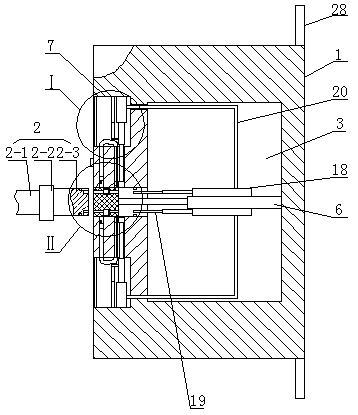
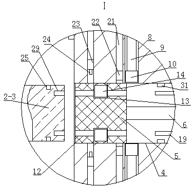
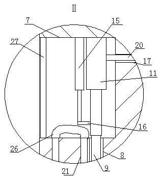
[0016]The safe charging device for new energy electric vehicles, as shown in the figure, includes a charging device housing 1 and a charging gun head 2. There is a cavity 3 inside the housing 1, and a square hole 4 is opened in the middle of the left end of the housing 3. The square hole 4 There is a square slider 5 inside. The square slider 5 is ...


PUM


Abstract

A new energy electric vehicle safety charging device includes a housing of a charging device and a charging gun head, acavity is arrange inside the shell, the center of A left end face of that house is provided with a square hole, A square slider is arranged in the square hole, the square slider is of slightly deformable material, the right end of the square slider is fixedly connected with the right wall of the cavity through an elastic telescopic rod, grooves are symmetrically formed on the upper and lower sides of the square hole on the left end face of the shell, the inner upper and lowersides of the square hole are symmetrically formed with first through holes, and vertical rods are arranged in the first through holes. As the new energy electric vehicle safety charging device is simple and small in structure, is easy to install, is ingenious in design, can ensure the safety of electric vehicle when charging; When the charging device is not charged, the square hole responsible forplugging and charging of the charging device can be automatically sealed to prevent dust and other impurities from enter the inside of the device, so as to ensure the cleanness of the inside of the device, prevent dust deposited on the internal power supply parts from affecting the stability of the electric connection during charging, and thus ensuring the safety of charging.

Description

technical field [0001] The invention belongs to the technical field of charging devices, in particular to a safe charging device for new energy electric vehicles. Background technique [0002] With the low-carbon economy becoming the main theme of my country's economic development, electric vehicles can reduce oil consumption and reduce polluting gas emissions, and have become a vigorously developed industry in my country. The electric vehicle charging station provides energy supply for the operation of electric vehicles and is a necessary supporting facility for the development of electric vehicles. The existing charging piles are relatively large in size and are placed next to the parking space, occupying a large land area. With the tightness of the parking space on the ground, the limited parking space will be more cramped after the charging pile is installed, and it will inevitably be blocked during use. Electric vehicles collide, causing damage to charging piles and ca...

Claims


Application Information

Patent Timeline
IPC IPC(8): B60L11/18
CPCY02T10/70Y02T10/7072Y02T90/14
Inventor 牛吉海李杰
Owner 临沭县益兴供汽维修服务有限公司
Learn More