
An assembled improved torpedo anchor

A prefabricated, torpedo technology, used in anchor points, transportation and packaging, ship construction, etc., can solve the problems of waste of resources, bulky anchor body, fixed and unadjustable anchor hole positions, etc., to overcome poor versatility and reduce production and manufacturing. cost effect

Pending Publication Date: 2018-12-07
CHONGQING UNIV +1
View PDF0 Cites 5 Cited by
  • Summary
  • Abstract
  • Description
  • Claims
  • Application Information

AI Technical Summary

Problems solved by technology

Due to the large size of the anchor body (the length of the anchor body is about 12-17 meters and the diameter is about 0.5-1.2 meters), its land and sea transportation costs are high
[0005] 2) The existing torpedo anchor only has a single anchor hole, and the position of the anchor hole is fixed and cannot be adjusted (in order to facilitate the installation and recovery of the anchor, the anchor hole is usually located at the tail end of the anchor, away from the center of mass of the anchor body, so the anchor body can The obtained pull-out capacity is not optimal)
When the application conditions change greatly, the torpedo anchor needs to be redesigned and manufactured, and the versatility is not strong enough, which is easy to cause waste of resources

Method used


Image

  • An assembled improved torpedo anchor
  • An assembled improved torpedo anchor
  • An assembled improved torpedo anchor

Examples


Embodiment 1

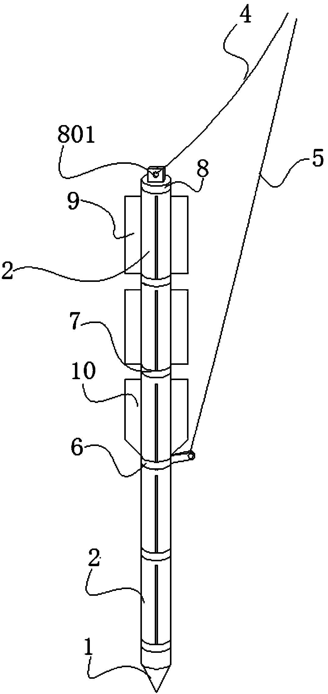
[0051] An assembled improved torpedo anchor is characterized in that: the assembled improved torpedo anchor 100 mainly includes an anchor head 1, several anchor body units 2, a metal ring 16, a tail end connecting portion 8, several anchor fins 19 and several anchor fins II10.

[0052] The lower end of the anchor head 1 is a tip, and the upper end has a rod body with a diameter smaller than that of the main body; the upper part of the rod body is a threaded part 101 , and the lower part is a cylinder 102 without thread. The shape of the tip of the anchor head 1 is cone, pyramid, oval or truncated oval.

[0053] The main body of the anchor unit 2 is a cylinder with a cavity inside. The upper end of the anchor unit 2 has a rod with a diameter smaller than that of the main body. The upper part of the rod body is a threaded part 202 , and the lower part is a cylinder 203 without thread. The side wall of the anchor unit 2 has several bar-shaped slots 201 . The notch at the lowe...

Embodiment 2

[0064] The main structure of this embodiment is the same as that of Embodiment 1, except that another connection method is adopted. That is, the anchor body units 2 are connected by piercing bolts 22 instead of threaded connections. The upper end of the anchor unit 2 has a connecting cylinder 207 . The connecting cylinder 207 has a through hole 2071 passing through two sides thereof. The lower end of the anchor unit 2 has a connecting hole 206 . The anchor unit 2 has through-holes 2061 running through its two sides. The pair of through holes 2061 are connected to the connection hole 206 .

[0065] When connecting, the connecting cylinder 207 of one anchor unit 2 is inserted into the connecting hole 206 of the other anchor unit 2 . The piercing bolts 22 pass through the piercing holes 2061 and 2071 to connect the two anchor units 2 .

Embodiment 3

[0067] The schematic diagram of the use of the assembled improved torpedo anchor 100 of the present invention is as follows Figure 16 shown. The anchor chain is divided into an anchor chain I4 and an anchor chain II5, both of which are connected with the metal ring I6 and the tail end connecting part 8 respectively. During installation, the torpedo anchor is hoisted to the design height by the anchor chain I4 and released to allow it to fall freely and vertically into the water. The assembled improved torpedo anchor 100 penetrates into the soil at the seabed level 300 under the action of its own weight and the kinetic energy obtained by free falling in the water. Finally complete the torpedo installation process. After the installation is completed, the torpedo anchor enters the working stage immediately. At this time, the ocean platform is connected to the anchor hole II 6021 on the metal ring I 6 of the torpedo anchor through the anchor chain II5. In order to obtain the ...


PUM


Abstract

The invention provides an assembled improved torpedo anchor. The assembled improved torpedo anchor mainly includes an anchor head, an anchor unit, a loading ring I and a loading ring II. As well as aplurality of anchor tab I and anchor tab II, modularization and standardized production can be realize, and manufacturing cost can be reduced, especially that transportation cost of land and sea. As that position of the work anchor hole of the invention can be adjusted along the length direction of the anchor body, the anchor hole can be rotate freely along the ring direction of the anchor body, and the drawing bearing capacity can be optimized. The length and weight of the anchor can be adjusted according to the demand, so as to meet the requirements of bearing capacity of various types of offshore platforms under various complex marine geological conditions. At the same time, the anchor flaps can be installed on demand, so as to meet the fluid stability requirements of anchor vertical installation under different ocean currents. In addition to the working anchor hole, the anchor hole is also arranged at the tail part of the anchor so as to facilitate the vertical installation of theanchor and optimize the recovery of the anchor. The invention has the characteristics of universality and strong recoverability, fully utilizes resources, and reduces production and use cost.

Description

technical field [0001] The present invention relates to marine deep water anchor foundation. Background technique [0002] With the rapid development of my country's economy, the consumption of oil and gas resources is increasing rapidly, and the exploitation of oil and gas is gradually moving from shallow sea to deep sea. The exploitation of offshore deepwater oil and gas resources has high requirements on oil platforms and platform anchoring foundations. For the comprehensive consideration of cost and efficiency, most deep-water mooring systems adopt taut-leg or semi-taut leg mooring instead of traditional catenary mooring. Different from catenary mooring, tensioned or semi-tensioned mooring requires the anchor foundation to have a large oblique uplift capacity (that is, both vertical and horizontal uplift capacity components). At present, the widely used deepwater anchor foundations mainly include suction anchors, normal load-bearing anchors, suction penetration plate a...

Claims


Application Information

Patent Timeline
Patent Type & Authority Applications(China)
IPC IPC(8): B63B21/24B63B21/26B63B21/48
CPCB63B21/24B63B21/26B63B21/48
Inventor 易江涛柳超凡杨红兵盛红星曹明洋
Owner CHONGQING UNIV
Learn More