Frictional resistance measuring system and method based on flexible micro beam

A frictional resistance and measurement system technology, applied in the direction of measuring force, measuring device, measuring fluid pressure, etc., can solve the problems of limiting the measurement range, reducing the measurement accuracy, brittle fracture of rigid silicon-based microstructure, etc., and achieves wide measurement range and measurement The effect of high precision and not easy to break and damage

Pending Publication Date: 2018-12-07
PEKING UNIV
View PDF11 Cites 4 Cited by
  • Summary
  • Abstract
  • Description
  • Claims
  • Application Information

AI Technical Summary

Problems solved by technology

However, since the calibration process of the MEMS-based floating wall shear stress sensor needs to exert a concentrated force on the floating unit, which is equivalent to the effect of shear stress, the tiny size of the floating unit limits the loading of the concentrated force, which greatly reduces the Measurement accuracy, moreover, the rigid silicon-based microstructure processed by MEMS is prone to brittle fracture, limiting the measurement range

Method used


Image

  • Frictional resistance measuring system and method based on flexible micro beam
  • Frictional resistance measuring system and method based on flexible micro beam
  • Frictional resistance measuring system and method based on flexible micro beam

Examples


Embodiment Construction

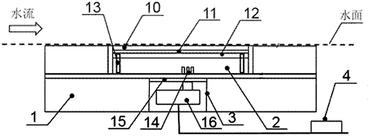
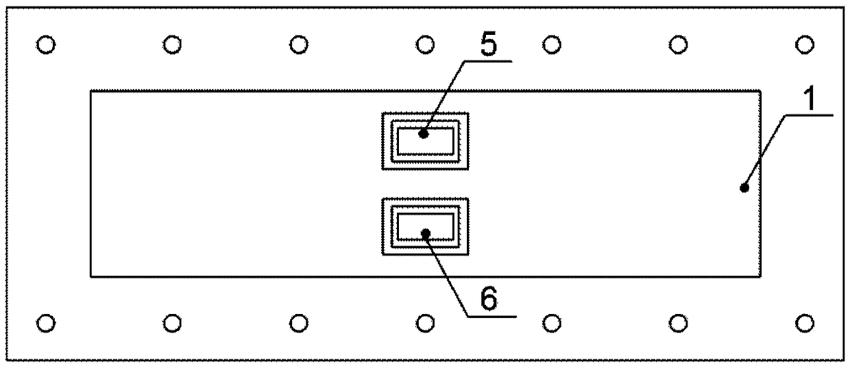
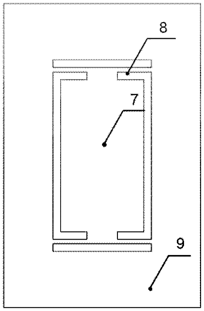
[0049] Most of the existing technologies use wall shear stress sensors based on MEMS, which have the defects of limited measurement accuracy, complicated calibration, and limited measurement range. In view of this, the present invention provides a friction resistance measurement system and method based on flexible microbeams. According to the displacement along the flow direction of the sample to be tested and the microbeam, the invention can measure the frictional resistance of the sample to be tested, has high sensitivity, high dynamic response, less interference by external temperature and pressure, easy calibration, and high measurement accuracy. At the same time, it can solve the problem that the traditional friction resistance measurement method can only measure smooth surfaces, and meets the needs of in-situ resistance measurement for samples to be tested on surfaces with different complex shapes.

[0050] In order to make the object, technical solution and advantages of...


PUM

PropertyMeasurementUnit
elastic modulusaaaaaaaaaa

Abstract

A frictional resistance measuring system based on a flexible micro beam comprises a medium platform, a measuring module, and a data processing module. The interior of the medium platform is filled with a fluid medium, the bottom of the medium platform is provided with openings, to-be-tested samples are placed inside the openings, and the fluid medium flows through the to-be-tested samples; the measuring module is located under the to-be-tested samples, the measuring module comprises a flexible micro beam and a floating plate, the flexible micro beam supports the floating plate, the to-be-tested samples are fixed on the floating plate, because the surfaces of the to-be-tested samples are subjected to the fluid frictional resistance in the fluid medium, the to-be-tested samples and the microbeam are enabled to generate displacement along the flow direction, and the measuring module is used to measure the displacement; and the data processing module displays the displacement and determines the frictional resistance according to the displacement. The system can measure the frictional resistance of the to-be-tested samples according to the displacement in the flow direction generated by the to-be-tested samples and the micro beam, and has advantages of high sensitivity, high dynamic response, less interference by external temperature and pressure, easy calibration, high measurementprecision, and the like.

Description

technical field [0001] The invention relates to a system for measuring frictional resistance near a wall, in particular to a system and method for measuring frictional resistance based on flexible microbeams. Background technique [0002] In fluid media, for example, the frictional resistance near the wall in the water flow field accounts for about 70% of the total resistance. Therefore, the characteristics of drag reduction and cavitation of underwater moving objects are important factors in hydrodynamics, fluid engineering and biofluid mechanics. The in-situ accurate measurement of near-wall frictional resistance is of great significance to the study of hydrodynamic characteristics and drag reduction mechanism. In recent years, the measurement technology of near-wall frictional resistance in the flow field has attracted widespread attention from all over the world. DARPA in the United States has set up a special project to develop in-situ frictional resistance measurement ...

Claims


Application Information

Patent Timeline
Patent Type & Authority Applications(China)
IPC IPC(8): G01L1/00G01L19/00
CPCG01L1/00G01L19/00
Inventor 段慧玲李宏源吕鹏宇袁辉靖李锡英杜增智程杨洋相耀磊刘焕
Owner PEKING UNIV
Why Eureka
Try Eureka