
Radar main lobe interference suppression method based on neural network

A neural network and main lobe interference technology, applied in the field of radar, can solve the problems of main beam deformation peak, difficult processing, and zero trapping

Inactive Publication Date: 2018-12-07
UNIV OF ELECTRONICS SCI & TECH OF CHINA
View PDF6 Cites 15 Cited by
  • Summary
  • Abstract
  • Description
  • Claims
  • Application Information

AI Technical Summary

Problems solved by technology

Mainlobe interference, on the other hand, has been less studied and is more difficult to deal with because it lies within the main beam
When there is main lobe interference, the adaptive beamforming method can also form a null in the main lobe interference direction, but at the same time, there will be adverse effects such as increased side lobe level, main beam deformation, and peak shift.
[0003] The earliest research on low sidelobe was aimed at linear arrays. The simplest and most easy-to-use method is the numerical analysis method using windowing function. For main lobe interference, adaptive digital beamforming technology can be used to make the main lobe direction produce zero traps. , but this method distorts the main beam; later S.J.YU proposed the blocking matrix method to overcome the problem of signal mixing in the covariance matrix during beamforming, so that the main beam does not distort when there is main lobe interference, but this method does not work in Nulling at main lobe interference locations

Method used


Image

  • Radar main lobe interference suppression method based on neural network
  • Radar main lobe interference suppression method based on neural network
  • Radar main lobe interference suppression method based on neural network

Examples


Embodiment Construction

[0024] A neural network-based main lobe interference suppression method of the present invention will be described in detail below in conjunction with the accompanying drawings.

[0025] A kind of main lobe interference suppression method based on neural network of the present invention, comprises the steps:

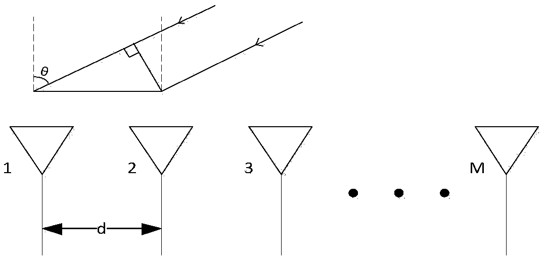
[0026] 1) if figure 1 As shown, according to the geometric model of the radar, the arrangement of the array elements is determined. Here, the uniform linear array is used as the model for analysis. figure 1 The uniform linear array in is composed of M identical omni-directional antenna elements that are evenly distributed on a straight line. The first array element is selected as the reference array element, and the array element numbers are m=1,2,3,..., M; the array element spacing is d. For specific analysis, M=17, λ is the input signal wavelength.

[0027] 2) According to the array element arrangement given in step 1), the main lobe width is about 5.9°, and th...


PUM


Abstract

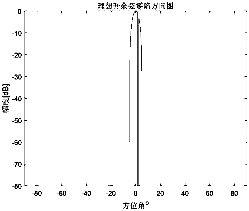
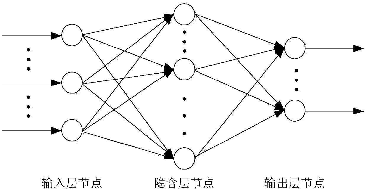
The invention discloses a radar main lobe interference suppression method based on a neural network and belongs to the technical field of radar. The method comprises a step of determining a steering vector of a received signal according to a geometric model of a radar array element arrangement after a main lobe interference direction is known and constructing a received signal model of the targetsignal and an interference signal, a step of constructing an ideal low side lobe null steering directional diagram according to the known main lobe interference direction, a step of creating a training sample through an input signal, taking the ideal low side lobe null steering directional diagram as an expected signal sample, establishing a suitable neural network model on the above basis and training, and a step of applying the trained neural network and verifying the input signal to obtain an output directional diagram. According to the method, the neural network is employed to suppress themain lobe interference, compared with the conventional method, the method of the invention has the advantages that null steering is formed at an interference position, the shape preserving of a mainlobe directional diagram and a low side lobe level are achieved, an ideal directional diagram is obtained, the accuracy of the angle measurement is improved, the energy loss of a target signal is reduced, the stability of a system is improved, the requirements of angle measurement can be satisfied well, and therefore, the system performance is improved.

Description

technical field [0001] The invention belongs to the technical field of radar, and relates to a main lobe interference suppression method, which can be used to form a null at the interference place when the interference direction is known, and keep the main lobe pattern conformal. Background technique [0002] Anti-jamming technology is an important branch in the field of array signal processing. There are many kinds of interference sources, and there are different classification methods according to different classification standards. According to their positions in the beam, they can be divided into main lobe interference and side lobe interference. Whether it is main lobe interference or side lobe interference, when it exists, it will affect the detection and processing of the target signal. The methods for anti-sidelobe interference have been studied in depth, such as adaptive beamforming and generalized sidelobe cancellation. Mainlobe interference, on the other hand, ha...

Claims


Application Information

Patent Timeline
Patent Type & Authority Applications(China)
IPC IPC(8): G01S7/28G01S7/292G01S7/35
CPCG01S7/2813G01S7/2923G01S7/354
Inventor 江朝抒李嘉辛
Owner UNIV OF ELECTRONICS SCI & TECH OF CHINA
Learn More