
Polarizing light splitting device

A polarization beam splitting device and polarized light technology, which is applied in the field of optical communication and fiber optic sensing, can solve the problems of large insertion loss, single beam splitter, and affecting the performance of fiber optic gyroscopes, and achieve small additional loss, high polarization extinction ratio, and high Effect of wavelength bandwidth

Active Publication Date: 2018-12-07
武汉嘉迅光电有限公司
View PDF4 Cites 5 Cited by
  • Summary
  • Abstract
  • Description
  • Claims
  • Application Information

AI Technical Summary

Problems solved by technology

[0002] Currently, on the market, most optical splitters are single-function optical power splitting or polarization beam splitting products, but there are few reports on low-loss polarization-independent one-to-two optical splitters with both optical power splitting and polarization beam splitting functions.
Among the existing products, the lithium niobate Y waveguide is the optical splitter in the inertial navigation fiber optic gyroscope, which has the functions of polarization beam splitting and optical power splitting at the same time. It has a high extinction ratio, but the insertion loss is very large.
And the lithium niobate Y waveguide only allows the waveguide mode of a single polarization to pass through, so there is always an inherent insertion loss close to 3dB for low-polarization light sources, which directly affects the performance of the fiber optic gyroscope

Method used


Image

  • Polarizing light splitting device
  • Polarizing light splitting device
  • Polarizing light splitting device

Examples

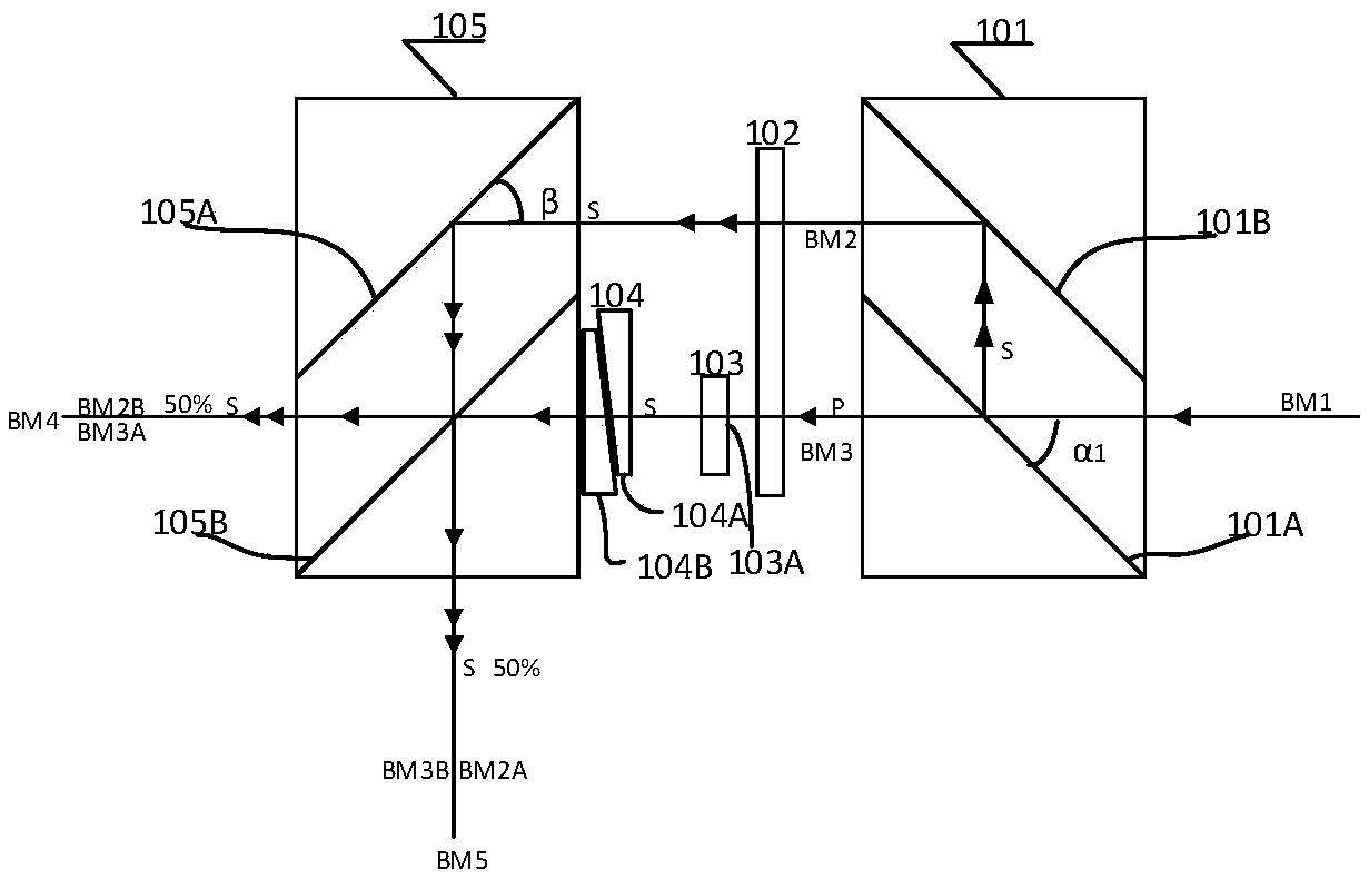
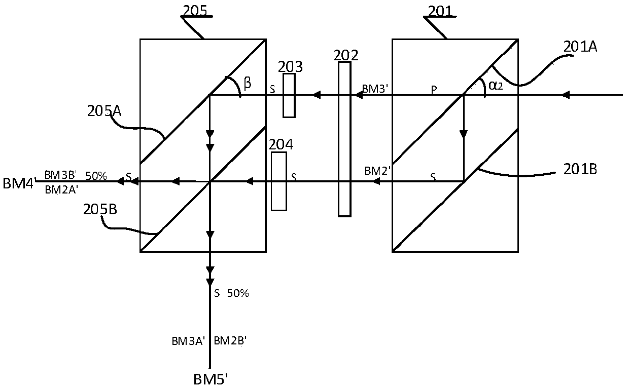
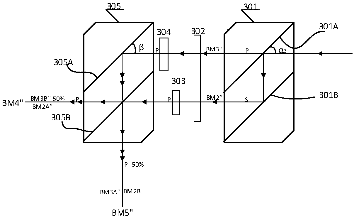

Embodiment Construction

[0027] The present invention is further described in conjunction with the following examples.

[0028] The inventor noticed that commercially available polarization beam splitters have a problem of close to 3dB intrinsic insertion loss for low-polarized light sources, and therefore proposed a polarization beam splitter with lower insertion loss. This polarization-independent broadband polarizing device can achieve the same polarization state and the same splitting ratio output for wide-spectrum natural light and linearly polarized light in various polarization directions, and has a higher polarization extinction ratio and wavelength bandwidth, that is, the splitting ratio is in Insensitive to wavelength in a wide wavelength range.

[0029] A polarization beam splitting device provided according to an embodiment of the present invention includes: a polarization beam splitter, a polarization rotator, and a single polarization beam splitter arranged in sequence.

[0030] The inc...


PUM


Abstract

The present invention provides a polarizing light splitting device comprising: a polarizing beam splitter, a polarizing rotator and a single polarization light splitter that are arranged in sequence.The device is small in additional loss and high in polarization extinction ratio, an input light beam in any polarization state can be split into two beams of linearly polarized lights, a light splitting ratio is hardly affected by the polarization state of an incident light beam, and the device is high in wavelength bandwidth and can be widely applied to the fields of optical fiber communications, optical fiber sensing, scientific research and the like.

Description

technical field [0001] The invention relates to the technical fields of optical communication and optical fiber sensing, in particular to a polarization splitting device. Background technique [0002] Currently, on the market, most optical splitters are single-function optical power splitting or polarization beam splitting products, but there are few reports on low-loss polarization-independent one-to-two optical splitters that have both optical power splitting and polarization beam splitting functions. Among the existing products, the lithium niobate Y waveguide is a beam splitter in the inertial navigation fiber optic gyroscope with both polarization beam splitting and optical power splitting functions. It has a high extinction ratio, but has a large insertion loss. In addition, the lithium niobate Y waveguide only allows the waveguide mode of a single polarization to pass through, so there is always an inherent insertion loss close to 3dB for low-polarization light source...

Claims


Application Information

Patent Timeline
Patent Type & Authority Applications(China)
IPC IPC(8): G02B27/28
CPCG02B27/283
Inventor 阚菁
Owner 武汉嘉迅光电有限公司
Learn More