Parking stall indication system based on quick stop

A parking space and indication technology, which is applied to the traffic control system of road vehicles, the buildings where cars are parked, and the direction of each open space in the parking lot. Effect of improving usability, improving parking efficiency and practicality

Active Publication Date: 2018-12-07
五莲县辉达机械有限公司
View PDF9 Cites 0 Cited by
  • Summary
  • Abstract
  • Description
  • Claims
  • Application Information

AI Technical Summary

Problems solved by technology

In the prior art, there are generally multiple parking spaces in the parking lot, but due to the large area of ​​the parking lot, it is difficult for the driver sitting in the car to quickly find the position of the empty parking space. In recent years, the frequency of extreme weather has increased, especially when there is hail or sun exposure. It is difficult to effectively protect parked vehicles in the existing outdoor parking lot area.

Method used


Image

  • Parking stall indication system based on quick stop
  • Parking stall indication system based on quick stop
  • Parking stall indication system based on quick stop

Examples


Embodiment 1

[0032] The following is a description of Embodiment 1.

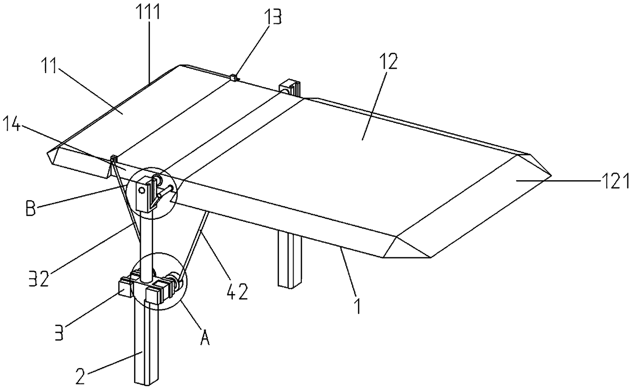
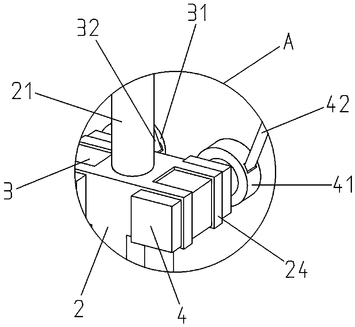
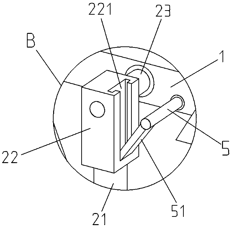
[0033] Such as Figures 1 to 7 As shown, a parking space indication system based on fast parking includes a protective plate 1, a rotating rear plate 11, a rear inclined plate 111, a rotating front plate 12, a front inclined plate 121, a positioning block 13, a lifting module 2, a lifting rod 21, Mounting block 22, inner T-shaped chute 221, rotating shaft 23, fixed frame one 24, rear wheel drive module 3, rear winding wheel module 31, rear plate driving steel wire 32, front wheel drive module 4, front winding wheel module 41, Front plate driving steel wire 42, supporting extension rod 5, supporting sliding rod 51, single-chip microcomputer control module 7, data storage module 71, relay 72, parking space infrared sensor 8, power supply 9, described lifting module 2 is provided with two and The bottom is respectively fixed on the ground, and the two sides of the lifting module 2 top are respectively provided with a fixed...

Embodiment 2

[0038] The following is a description of Embodiment 2.

[0039] In embodiment 2, for the same structure as in embodiment 1, give the same symbol, omit the same description, embodiment 2 has made improvement on the basis of embodiment 1, as Figures 8 to 9 As shown, the rear wheel drive module 3 and the front wheel drive module 4 and their auxiliary structures are canceled, and the rear part of the installation block 22 is respectively provided with two fixed frames 223, and the two fixed frames 223 are provided with a driving rotary motor 6. The rotary drive motor 6 is provided with a rotary drive rod 61 facing the mounting block 22, the rotary drive rod 61 extends through the mounting block 22, and the distal ends are respectively located on both sides of the protective plate 1 on the rotating front plate 12 is connected to the junction of the rotating rear plate 11, and the mounting block 22 is provided with a vertical outer T-shaped chute 222 on the side facing the rotating...

Embodiment 3

[0042] The following is a description of Embodiment 3.

[0043] In embodiment 3, for the same structure as in embodiment 1 and 2, the same symbol is given, and the same description is omitted. Embodiment 3 is improved on the basis of embodiment 1 and 2. The protective plate 1 The inner side is also provided with a horizontal sensor for detecting the tilt angle, and the horizontal sensor is electrically connected with the input end of the single-chip microcomputer control module 7 .

[0044] The advantage of this embodiment is that the inclination angle of the protective plate 1 detected by the level sensor can be transmitted to the single-chip control module 7 in real time, and the single-chip control module 7 can further control and drive the rotary motor 6 or the rear wheel drive module 3 and the front wheel. The driving module 4 further realizes the angle control of the protective plate 1 more conveniently, which greatly improves the functionality and practicability.

[00...


PUM


Abstract

The present invention provides a parking stall indication system based on quick stop, belonging to the technical field of vehicle parking. The system comprises a control module and an indication model, an input end of the control module is electrically connected with an induction module, the induction module is arranged at the front side of the indication module, and the indication module is connected with a rotation drive module which is electrically connected with an output end of the control module. The problem is solved that parking stall searching wastes time in a current parking lot, andthe parking stall indication system based on quick stop can rapidly obtain position information of empty parking stalls near after vehicle enter a parking area so as to effectively reduce the tedioussearching of the parking stalls, have a protection effect on the parking vehicles and improve the parking efficiency and practicability.

Description

technical field [0001] The invention relates to a parking space indication system based on fast parking, belonging to the technical field of vehicle parking. Background technique [0002] At present, with the continuous improvement of living standards, private cars have become one of the important means of transportation for people's life and travel. Many places have set up parking areas to ensure that vehicles are parked in an orderly manner. In the prior art, there are generally multiple parking spaces in the parking lot, but due to the large area of ​​the parking lot, it is difficult for the driver sitting in the car to quickly find the position of the empty parking space. In recent years, the frequency of extreme weather has increased, especially when there is hail or sun exposure. It is difficult for the existing outdoor parking lot area to provide effective protection for parked vehicles. [0003] Aiming at the above existing technical conditions, the applicant of the...

Claims


Application Information

Patent Timeline
Patent Type & Authority Applications(China)
IPC IPC(8): G08G1/14E04H6/18
CPCE04H6/18G08G1/14G08G1/141
Inventor 孙洪涛
Owner 五莲县辉达机械有限公司
Why Eureka
Try Eureka