Voltage sampling circuit and circuit system
A sampling circuit and voltage sampling technology, applied in the field of communication, can solve the problem of uneven voltage of each BUS, and achieve the effect of voltage stability
- Summary
- Abstract
- Description
- Claims
- Application Information
AI Technical Summary
Problems solved by technology
Method used
Image
Examples
Embodiment 1
[0026] This application document provides a voltage sampling circuit, which can be applied to the voltage sampling of multiple PFC series input bus circuits BUS, that is, there are multiple BUS circuits, and each BUS circuit can be sampled according to the voltage recorded in this embodiment. The circuit is set.
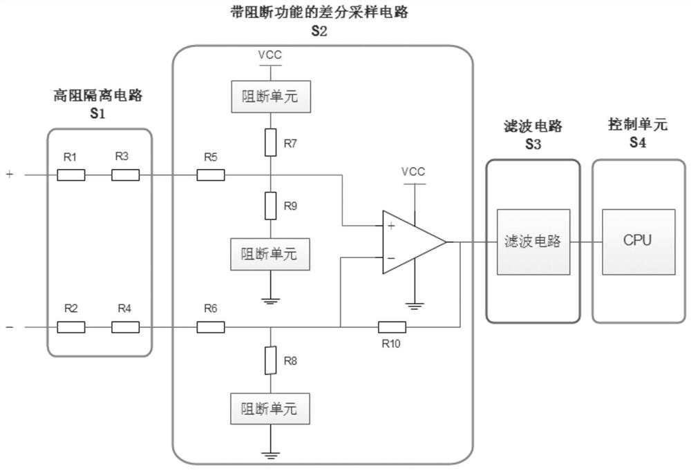
[0027] In this embodiment, a voltage sampling circuit is provided, figure 1 is a schematic diagram of a voltage sampling circuit according to an embodiment of the present invention, such as figure 1 As shown, the process includes the following steps: the voltage sampling circuit may include four parts:
[0028] S1, high resistance isolation circuit; S2, differential sampling circuit with blocking unit; S3, filter circuit; S4, control unit.
[0029] In the above S2 part, the differential sampling circuit for sampling the BUS circuit is shown, wherein, at the connection between the differential sampling circuit and other BUS circuits, a blocking unit is provided on t...
specific Embodiment approach
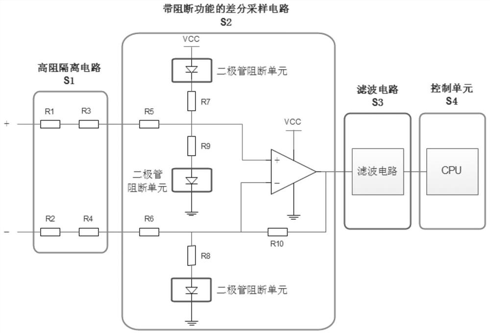
[0047] figure 2 It is a structural block diagram of a multi-channel serial BUS voltage sampling circuit with a blocking function according to a specific embodiment, such as figure 2 As shown, the voltage sampling circuit includes four parts, a high-impedance isolation circuit, a differential sampling circuit with a blocking function, a filter circuit, and a control unit, wherein the control unit includes DSP analog-to-digital conversion for loop calculation.
[0048] For a topology with multiple PFCs in series or similar functions, the BUS voltage sampling circuit with a blocking unit is a simple and effective sampling circuit. The circuit can be subdivided into four hardware units. attached figure 1 The hardware circuit in the circuit implements the isolation and sampling of the single-channel BUS voltage and sends the sampled voltage signal to the CPU for loop calculation after filtering.
[0049] The S1 module is an input resistor, which is a part of the differential s...
Embodiment 2
[0056] According to another embodiment of the present invention, a circuit system is provided, including the voltage sampling circuit described in any one of the above-mentioned embodiments.
[0057] Obviously, those skilled in the art should understand that each module or each step of the above-mentioned present invention can be realized by a general-purpose computing device, and they can be concentrated on a single computing device, or distributed in a network formed by multiple computing devices Alternatively, they may be implemented in program code executable by a computing device so that they may be stored in a storage device to be executed by a computing device, and in some cases in an order different from that shown here The steps shown or described are carried out, or they are separately fabricated into individual integrated circuit modules, or multiple modules or steps among them are fabricated into a single integrated circuit module for implementation. As such, the p...
PUM
 Abstract
Description
Claims
Application Information
 - R&D
- Intellectual Property
- Life Sciences
- Materials
- Tech Scout
- Unparalleled Data Quality
- Higher Quality Content
- 60% Fewer Hallucinations
Browse by: Latest US Patents, China's latest patents, Technical Efficacy Thesaurus, Application Domain, Technology Topic, Popular Technical Reports.
© 2025 PatSnap. All rights reserved.Legal|Privacy policy|Modern Slavery Act Transparency Statement|Sitemap|About US| Contact US: help@patsnap.com


