
Permanent magnet synchronous motor traction system

A permanent magnet synchronous motor, traction system technology, applied in the direction of motor, control system, AC motor control, etc., to slow down the current rising rate, suppress the moment of heavy input, and increase the circuit time constant.

Pending Publication Date: 2018-12-07
CRRC XIAN YONGEJIETONG ELECTRIC CO LTD
View PDF0 Cites 1 Cited by
  • Summary
  • Abstract
  • Description
  • Claims
  • Application Information

AI Technical Summary

Problems solved by technology

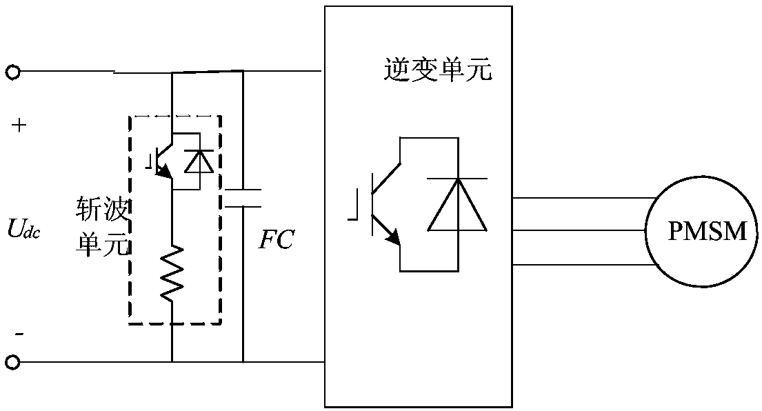
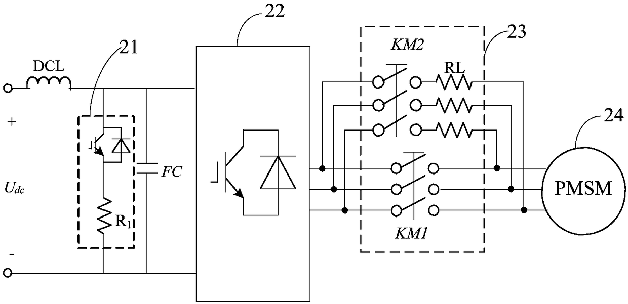
[0005] The embodiment of the present invention provides a permanent magnet synchronous motor traction system, the purpose of which is to solve the high-speed power failure-restart problem of the permanent magnet synchronous motor traction system in rail transit

Method used


Image

  • Permanent magnet synchronous motor traction system
  • Permanent magnet synchronous motor traction system

Examples


Embodiment Construction

[0021] In order to make the purpose, technical solutions and advantages of the embodiments of the present invention clearer, the technical solutions in the embodiments of the present invention will be clearly and completely described below in conjunction with the drawings in the embodiments of the present invention. Obviously, the described embodiments It is a part of embodiments of the present invention, but not all embodiments. Based on the embodiments of the present invention, all other embodiments obtained by persons of ordinary skill in the art without making creative efforts belong to the protection scope of the present invention.

[0022] When rail transit vehicles run between actual line stations, their operating conditions generally experience traction-coasting-braking (or re-traction), where the idling condition refers to the traction motor output torque is zero, relying on the vehicle's inertial operation. In the traditional asynchronous traction system, in the idli...


PUM


Abstract

The invention provides a permanent magnet synchronous motor traction system. During the application process in the rail transit field, when IGBT pulses need to be blocked and an inverter unit needs tobe powered off and enter idle running, a first three-phase contactor and a second three-phase contactor in a system reput-into-service unit are disconnected. When reput-into-service is required, thefirst three-phase contactor can be directly put into service if a permanent magnet synchronous motor is running at low speed, the reput-into-service is carried out, the second three-phase contactor does not operate, and a disconnecting state is maintained; and if the permanent magnet synchronous motor is running at a high speed, the second three-phase contactor can be directly put into service, amotor stator performs current limiting and voltage division by means of resistors serially connected with phases of the second three-phase contactor, or slow down the current rise rate by means of inductors serially connected with phases of the second three-phase contactor, and increases circuit time constant, thereby suppressing overcurrent or overvoltage faults caused by too fast rise of motor stator current and DC side bus voltage at the reput-into-service moment.

Description

technical field [0001] The invention relates to motor drive and control technology, in particular to a permanent magnet synchronous motor (Permanent Magnetic Synchronous Machine, PMSM) traction system. Background technique [0002] In recent years, the state has vigorously promoted the relevant policies of "energy saving, emission reduction, and green travel". The efficiency of the electric traction system is improved, which can effectively save energy consumption. Compared with asynchronous motors, permanent magnet synchronous motors do not need to consume additional excitation current. Therefore, the traction system using permanent magnet synchronous motors can meet the requirements of high efficiency, energy saving and high energy density. And because the permanent magnet synchronous motor rotor does not pass current, the rotor itself does not generate heat, so the permanent magnet synchronous motor can realize a fully enclosed design. Good dustproof and heat dissipatio...

Claims


Application Information

Patent Timeline
IPC IPC(8): H02P6/08H02P25/022B60L15/00
CPCH02P6/08B60L15/00Y02T10/64Y02T10/72
Inventor 侯晓军王雨琦
Owner CRRC XIAN YONGEJIETONG ELECTRIC CO LTD
Learn More