
A Stability Compensation and Impedance Transformation Circuit of Oscillator Frequency Regulation Loop

An impedance transformation circuit and stability compensation technology, applied in the field of circuits, can solve the problems of low MOS tube working efficiency, MOS tube entering the linear region, and the output current cannot be kept constant.

Active Publication Date: 2022-04-05
CHONGQING PAIXINRUWEI TECH CO LTD
View PDF6 Cites 0 Cited by
  • Summary
  • Abstract
  • Description
  • Claims
  • Application Information

AI Technical Summary

Problems solved by technology

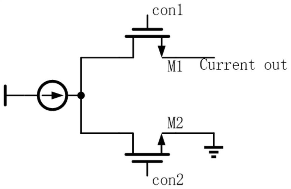
The disadvantage of the existing circuit is that when the current demand is too large or too small, the existing circuit will cause the MOS tube to enter the linear region, resulting in low working efficiency of the MOS tube. Since the current calculation formula of the above circuit is I=Vcon / R, where I is the output current, R is the resistance value of the resistor, and Vcon is the input control voltage
Since the current is limited, the input voltage range is also limited
[0004] And when the voltage changes greatly or oscillates, this change and oscillation will be transmitted to the gate and source of the MOS tube device, resulting in an inability to maintain a constant output current

Method used


Image

  • A Stability Compensation and Impedance Transformation Circuit of Oscillator Frequency Regulation Loop
  • A Stability Compensation and Impedance Transformation Circuit of Oscillator Frequency Regulation Loop
  • A Stability Compensation and Impedance Transformation Circuit of Oscillator Frequency Regulation Loop

Examples


Embodiment Construction

[0022] The following will be combined with Figure 1-Figure 3 The present invention is described in detail, and the technical solutions in the embodiments of the present invention are clearly and completely described. Apparently, the described embodiments are only some of the embodiments of the present invention, not all of them. Based on the embodiments of the present invention, all other embodiments obtained by persons of ordinary skill in the art without making creative efforts belong to the protection scope of the present invention.

[0023] The present invention provides a stability compensation and impedance transformation circuit of an oscillator frequency adjustment loop through improvement, mainly aimed at the instability of the currently used circuit when the phase-locked loop needs a large current, which may cause the performance of the phase-locked loop Made on the premise that it cannot meet the actual needs;

[0024] Commonly used circuits use the series connect...


PUM


Abstract

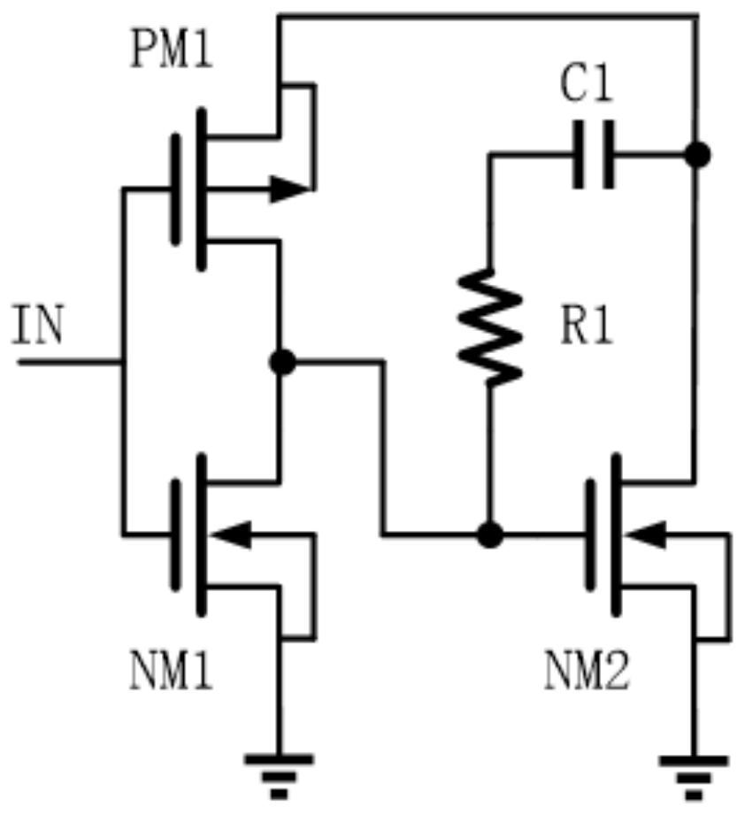
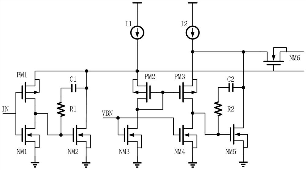
The invention discloses a stability compensation and impedance conversion circuit of an oscillator frequency adjustment loop; after the improvement, the input control voltage can float in a large range between VDD and GND, which is different from the input control voltage of the prior art which is limited Between less than VDD and greater than GND. A Miller capacitance is connected across the gate and drain of NM2 and NM5. Due to the Miller effect, the input capacitance of NM2 and NM5 becomes very large, resulting in the relatively high-frequency oscillation signal not being input. , so that the stability of the current output by the voltage-to-current module is relatively high. The circuit has the function of impedance transformation, which can improve the efficiency of the oscillator.

Description

technical field [0001] The invention relates to the related field of circuits, in particular to a stability compensation and impedance conversion circuit of an oscillator frequency adjustment loop. Background technique [0002] In most cases, the commonly used oscillation circuit in the phase-locked loop is the ring oscillator in the case of low requirements. Under normal circumstances, we use the current input to the ring oscillator to control the oscillation frequency of the oscillator. Since the signal passing through the loop filter is a voltage signal, we need a voltage-to-current module to change the control voltage signal. [0003] The existing and commonly used voltage-to-current module is usually composed of a MOS tube, an operational amplifier and a resistor, wherein the gate of the MOS is controlled by the output of the operational amplifier; the resistor is connected to the source of the MOS tube, and then connected to the On the power supply or the ground; the...

Claims


Application Information

Patent Timeline
Patent Type & Authority Patents(China)
IPC IPC(8): H03L7/099H03L1/00
CPCH03L1/00H03L7/099
Inventor 唐枋
Owner CHONGQING PAIXINRUWEI TECH CO LTD
Learn More