Ampoule bottle printing and placing device

A technology for ampoules and printing, which is applied in the direction of conveyor control devices, packaging, packaging bottles, etc. It can solve the problems of increasing employees, shortage of funds, and increasing labor, so as to facilitate installation and replacement, avoid unclear writing, Avoid the effect of ink not drying

Pending Publication Date: 2018-12-11
ZHENGZHOU SHUNYI TECH CO LTD
View PDF6 Cites 4 Cited by
  • Summary
  • Abstract
  • Description
  • Claims
  • Application Information

AI Technical Summary

Problems solved by technology

[0002] If there is a shortage of branches or characters during the printing process of the ampoule bottle, it will be necessary to add branches manually in the later stage after printing. After the ampoule bottle is printed, it needs to be placed in the groove of the box holder. Evenly put into the groove of the box holder, the box holder is usually conveyed by the conveyor belt, because there is a gap between the box holders, and there will be flanges on the top of the box holder, all the grooves in the current box holder are put into the ampoule bottle Finally, the groove of the next box support could not reach the position where the ampoule came down on time, resulting in some ampoules not being able to effectively enter the box support after printing, and the lack of support after being placed in the support also required manual addition, resulting in the increase of redundant staff and duplication Labor, increasing labor force, the problem of lack of support will not be ruled out, which will always lead to unstable drop of ampoules, increase the cost of employment, increase the production cost of medicines, and increase the cost of medication for patients

Method used


Image

  • Ampoule bottle printing and placing device
  • Ampoule bottle printing and placing device
  • Ampoule bottle printing and placing device

Examples


Embodiment 1

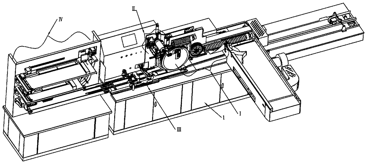
[0051] Embodiment 1, a kind of ampoule bottle printing and holding device, such as Figure 1-3 , including sequentially connected ampoule conveying mechanism I, printing mechanism II, sub-holding mechanism III and conveying-in-holding mechanism IV, the ampoule conveying mechanism I includes a frame 1 and a vertical plate 9 located behind the frame 1, the machine The primary conveying screw 2 and the first driving device 21 (prior art) that controls the rotation of the primary conveying screw 2 are installed on the frame 1, and one side of the frame 1 is provided with the head of the primary conveying screw 2 and stores The storage area 11 of the ampoule bottle, the bottom of the primary conveying screw 2 is a conveying platform 47, the tail of the primary conveying screw 2 is provided with a buffer mechanism installed on the vertical plate 9, and the bottom of the buffer mechanism is provided with Branch missing detection sensor 41 (prior art), the vertical plate 9 is provided...

Embodiment 2

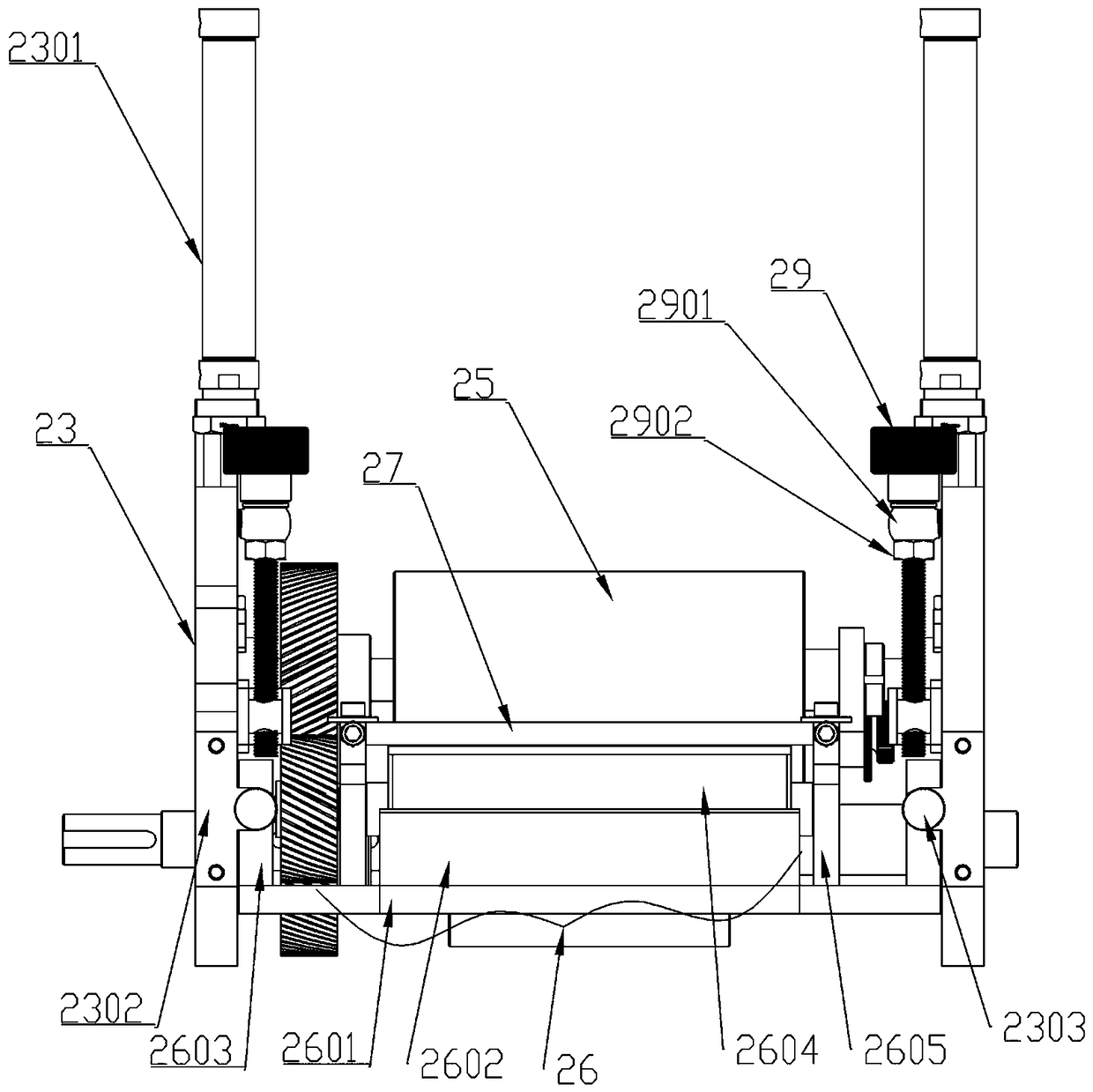
[0053] Embodiment two, such as Figure 11-16 , basically the same as the second embodiment, the difference is that the printing mechanism II includes an anilox roller 2604, a type roller 25 and A transfer roller 24, one end of the central axis of the transfer roller 24 is connected with a drive motor, and an ink cartridge mechanism 26 located below the anilox roller 2604 is arranged between the side plate supports 23 on both sides. One side of the anilox roller 2604 is provided with an ink scraping mechanism, and the ink cartridge mechanism 264 includes an ink storage box 2602 installed on the bottom plate 2601, and the ink storage box 2602 protrudes forward with an ink-staining groove located under the anilox roller 2604 2606, the ink scraping mechanism includes a scraper bracket 2605 located on both sides of the ink storage box 2602, a knife seat 27 with a scraper 2701 is installed above the scraper bracket 2605, and the scraper 2701 is connected to the net The pattern roll...

Embodiment 3

[0057] Embodiment three, such as Figure 17-20 , is basically the same as Embodiment 1 or 2, the difference is that the sub-support mechanism III includes a base 31 and a work frame 3101 fixed on the base 31, and the front of the work frame 3101 is provided with an upper and horizontally arranged Workbench, the top of the workbench is provided with a side push mechanism on the work frame 3101, and the work frame 3101 is provided with a chute 31011 matched with the side push mechanism, and the right side of the workbench Two separating baffles 36 are arranged oppositely, and the work frame 3101 is provided with a separation groove 31014 positioned on the right side of the workbench, and the right side of the separation baffle 36 is provided with and installed on the work frame 3101 and The adsorption mechanism that slides in the separation groove 31014, the right end of the workbench protrudes downwards and is fixed on the work frame 3101 and faces to the left side, the bottom ...


PUM


Abstract

The invention relates to an ampoule bottle printing and placing device. The ampoule bottle printing and placing device comprises an ampoule bottle conveying mechanism, a printing mechanism, a branch supporting mechanism and a conveying and feeding mechanism, wherein the ampoule bottle conveying mechanism, the printing mechanism, the branch supporting mechanism and the conveying and feeding mechanism are sequentially connected. The ampoule bottle printing and placing device can automatically carry out printing and packaging on ampoule bottles, wherein the ampoule bottle conveying mechanism temporarily stores the ampoule bottles through a buffer mechanism, is used for detecting whether lacking exists or not and does not affect the conveying of a secondary conveying screw rod, and the detected signal is fed back to a driver of a first driving device through a lacking detecting inductor; and once the lacking situation exists, the first driving device accelerates, fills gaps of lacking andensures that a storage track is always filled with the ampoule bottles. The circumference of a buffer wheel is covered with brushes so that the ampoule bottles can be pressed on the buffer track without damaging the ampoule bottles.

Description

technical field [0001] The invention belongs to the technical field of ampoule bottle production, and in particular relates to a printing and supporting device for ampoule bottles. Background technique [0002] If there is a shortage of branches or characters during the printing process of the ampoule bottle, it will be necessary to add branches manually in the later stage after printing. After the ampoule bottle is printed, it needs to be placed in the groove of the box holder. Evenly put into the groove of the box holder, the box holder is usually conveyed by the conveyor belt, because there is a gap between the box holders, and there will be flanges on the top of the box holder, all the grooves in the current box holder are put into the ampoule bottle Finally, the groove of the next box support could not reach the position where the ampoule came down on time, resulting in some ampoules not being able to effectively enter the box support after printing, and the lack of sup...

Claims


Application Information

Patent Timeline
Patent Type & Authority Applications(China)
IPC IPC(8): B65B63/00B65B21/04B65B51/14
CPCB65B21/04B65B51/14B65B63/005B65G43/08B65G47/261B65G2201/0244Y02P40/57
Inventor 刘丙炎
Owner ZHENGZHOU SHUNYI TECH CO LTD
Why Eureka
Try Eureka