The Method of Constructing the Floor Roof Using Aluminum Formwork
A technology of aluminum templates and aluminum molds, which is applied in the field preparation of formwork/formwork/work frames, building components, construction, etc., can solve the problems of low transfer efficiency, reduce labor intensity, improve construction efficiency, and avoid multiple The effect of repeated handling
- Summary
- Abstract
- Description
- Claims
- Application Information
AI Technical Summary
Problems solved by technology
Method used
Image
Examples
Embodiment 1
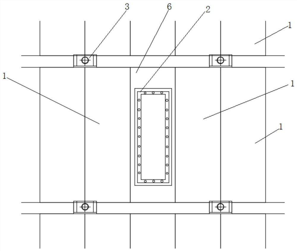
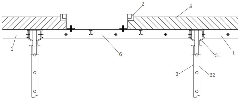
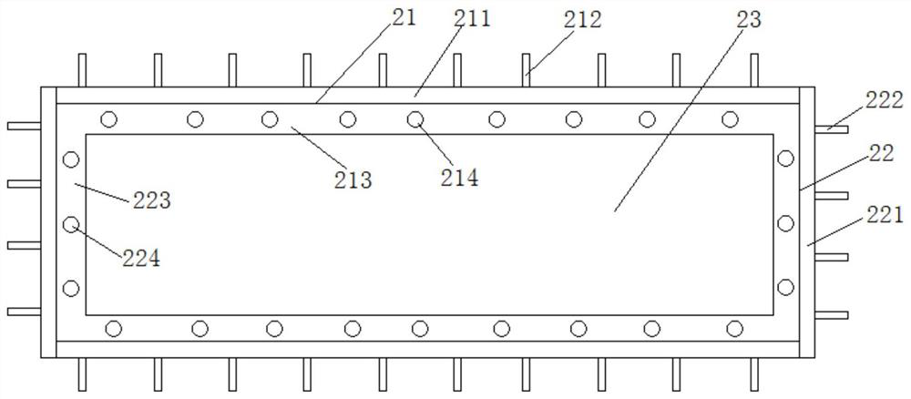
[0036] Such as Figure 1-2 As shown, the aluminum mold assembly 2 for making the bore is used, and when the top floor 4 is poured on the floor, the top panel 1 is placed on the top floor 4, including continuous tip, the lower support is uniform spacer. The top support device 3 includes a top support top holder 31 and a top rod 32 under the support top holder; the top template 1 is also provided with an aluminum mold assembly 2, when the top flossing 4 completes the pour It can form a tension hole on the top floor, and the lower floor is used to transfer aluminum templates and other building materials and small operating tools. Specifically, the aluminum mold assembly 2 includes a side plate 21 and a end plate 22, and a long square cavity 23 is coupled to each other. After the top floor 4 is poured, the aluminum mold assembly 2 and the top template 1 can be removed such that the feed hole is formed to facilitate the transfer of aluminum templates such as aluminum templates from the ...
Embodiment 2
[0043] Such as Figure 8-10As shown, the difference between the present embodiment and the first embodiment is mainly in that the aluminum template assembly is different. The aluminum mold assembly 7 for making the feed hole in the present embodiment is welded by aluminum template, and the overall is inverted hollow. Four prism structure; the aluminum template assembly 7 includes a four-priced assembly assembly 71, and a four-priced binding body 72, a quadritical assembly in the upper edge of the combination of the four prism The lower edge of the body 72 and the upper edge of the four pricers under the assembly 71 are connected between the horizontal step portion 73.
[0044] The outer side surface of the aluminum mold assembly 7 is formed with a plurality of vertical rubber plates 74, the bottom of the vertical ribs 74 located in the middle of the four pricers, and the top edge and the horizontal step portion. The lower surface of 73 is further connected; further, the outer side ...
Embodiment 3
[0049] Such as Figure 10 , 11 As shown, the top support device 3 includes a support top seat 31 and a top rod 32 that is supported in the support top seat 31, and the support top seat 31 can use some of the top seats having a support function, and in the present embodiment. Where Figure 11-12 As shown, the support top seat 31 includes a top base bottom plate 311, and two parallel intervals of two parallel intervals arranged longitudinally along the top seat bottom plate 311, the spacing between the two top seat clamp 312 is not less than two top templates. The total thickness of the template side panel at the 4-end connection, the support top seat 31 is inserted into the top rod 32 through the top seat support post 313 thereof, and the support top 31 can be supported when the end of the two top template 4 is aligned. The template side panel of the top template 4 is sandwiched between the two top seat clamp 312 to form an effective support.
[0050] The top seat bottom plate 311 is...
PUM
 Abstract
Description
Claims
Application Information
 - R&D
- Intellectual Property
- Life Sciences
- Materials
- Tech Scout
- Unparalleled Data Quality
- Higher Quality Content
- 60% Fewer Hallucinations
Browse by: Latest US Patents, China's latest patents, Technical Efficacy Thesaurus, Application Domain, Technology Topic, Popular Technical Reports.
© 2025 PatSnap. All rights reserved.Legal|Privacy policy|Modern Slavery Act Transparency Statement|Sitemap|About US| Contact US: help@patsnap.com


