

Electronic expansion valve
A technology of electronic expansion valve and valve needle, which is applied in the direction of lifting valve, valve device, lighting and heating equipment, etc., which can solve the problems of troublesome adjustment, complicated structure and assembly, and avoid the tight sealing of the valve port and high coaxiality , with a tight effect
- Summary
- Abstract
- Description
- Claims
- Application Information
AI Technical Summary
Problems solved by technology
Method used
Image

Examples
Embodiment 1
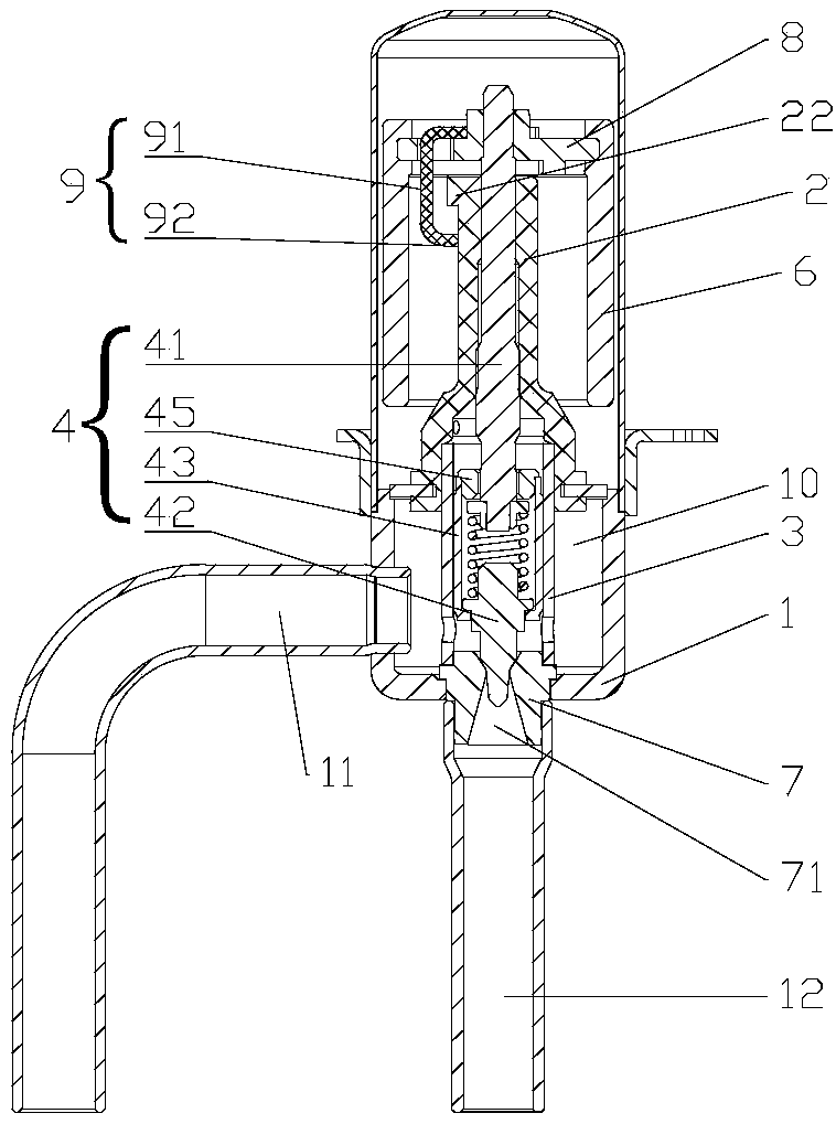
[0049] refer to figure 2 , the electronic expansion valve of this embodiment includes a valve body 1, a nut 2 assembled on the valve body 1, a valve needle assembly (including a screw rod 41 ) movably assembled in the nut 2, which is arranged on the periphery and covers the nut 2 Part of the magnetic rotor 6 and the guide sleeve 3, the magnetic rotor 6 is fixedly connected to the upper end of the screw rod 41 through the connecting plate 8, the magnetic rotor 6 drives the screw rod 41 to reciprocate up and down, and the control valve needle 42 is located relative to the valve body. 1 the opening of the valve port 71 at the bottom, so as to achieve the purpose of regulating the refrigerant flow.
[0050] The movable upper end stopper 9 is fixedly connected on the connecting plate 8, and extends downward from the connecting plate 8. The movable upper end stopper 9 includes a vertical extension 91 and a transverse limiter 92; The upper end of the outer periphery is also provide...
Embodiment 2
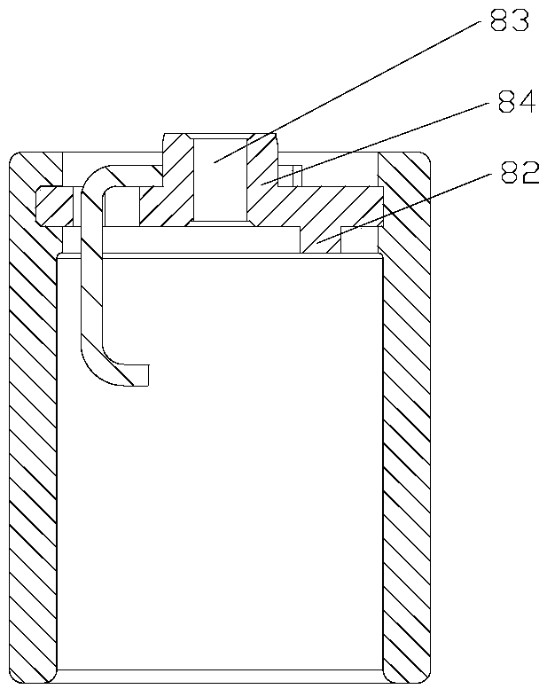
[0060] refer to Figure 8 , the structure of the electronic expansion valve in this embodiment is substantially the same as that in Embodiment 1, except that the movable upper end stopper 9 is connected from the side of the connecting plate 8 facing the nut 2 . The connecting plate is provided with a second protruding ring 85 around the hole 83 for threading the screw on one side of the nut, and the movable upper end stopper 9 includes a circular ring at the corresponding position, which can be an open ring or a closed ring , for being sleeved on the second protruding ring 85 . This setup is easier.
Embodiment 3
[0062] refer to Figure 9 and Figure 10 , the structure of the electronic expansion valve in this embodiment is substantially the same as that in Embodiment 1, the difference is that the expansion valve also includes a fixed lower end stopper 26, and its corresponding stopper 92 is fixed at a corresponding position on the outer circumference of the nut 2, The limit part 92 of the movable upper end stopper 9 also plays the role of a movable lower end stopper. Before reaching the minimum opening of the valve port, there is a gap between the limit part 92 of the movable upper end stopper 9 and the upper end surface of the fixed lower end stopper, which can pass above the fixed lower end stopper; when the minimum opening of the valve port is reached , the position-limiting portion 92 is blocked by the fixed lower end stopper and no longer rotates. At this moment, the screw mandrel 41 reaches the maximum degree of downward movement.
[0063] The movable upper end stopper 9 is co...
PUM
 Abstract
Description
Claims
Application Information