
Laser projection equipment

A technology of laser projection and equipment, applied in optics, image reproducer using projection device, instruments, etc., can solve problems such as image distortion

Pending Publication Date: 2018-12-11
GOERTEK OPTICAL TECH CO LTD
View PDF5 Cites 1 Cited by
  • Summary
  • Abstract
  • Description
  • Claims
  • Application Information

AI Technical Summary

Problems solved by technology

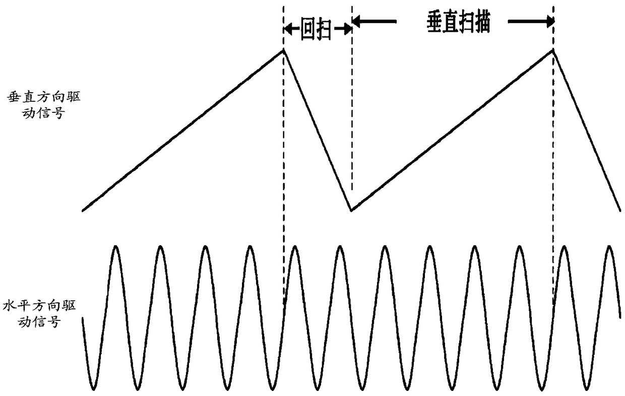
[0005] The embodiment of the present application provides a laser projection device to solve the technical problem of image distortion caused by the change of angular velocity of MEMS horizontal direction operation

Method used


Image

  • Laser projection equipment
  • Laser projection equipment
  • Laser projection equipment

Examples


Embodiment Construction

[0034] In order to enable those skilled in the art to better understand the solutions of the present application, the technical solutions in the embodiments of the present application will be clearly and completely described below in conjunction with the drawings in the embodiments of the present application.

[0035] In some processes described in the specification and claims of the present application and the description in the above-mentioned drawings, multiple operations appearing in a specific order are included, but it should be clearly understood that these operations may not be performed in the order in which they appear herein Execution or parallel execution, the serial numbers of the operations, such as 101, 102, etc., are only used to distinguish different operations, and the serial numbers themselves do not represent any execution order. Additionally, these processes can include more or fewer operations, and these operations can be performed sequentially or in paral...


PUM


Abstract

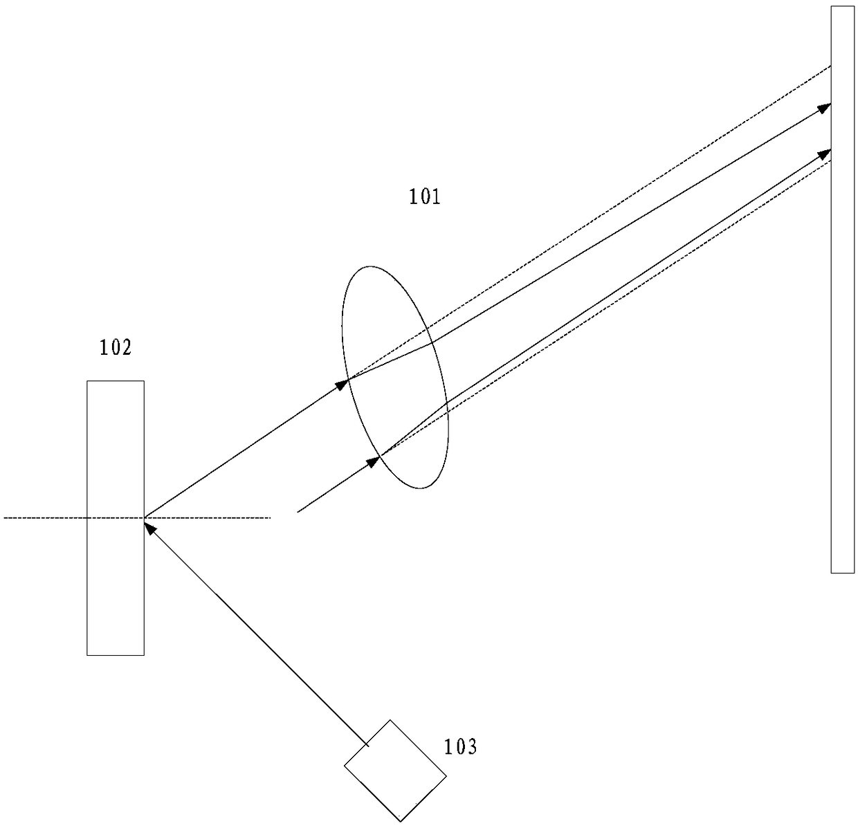
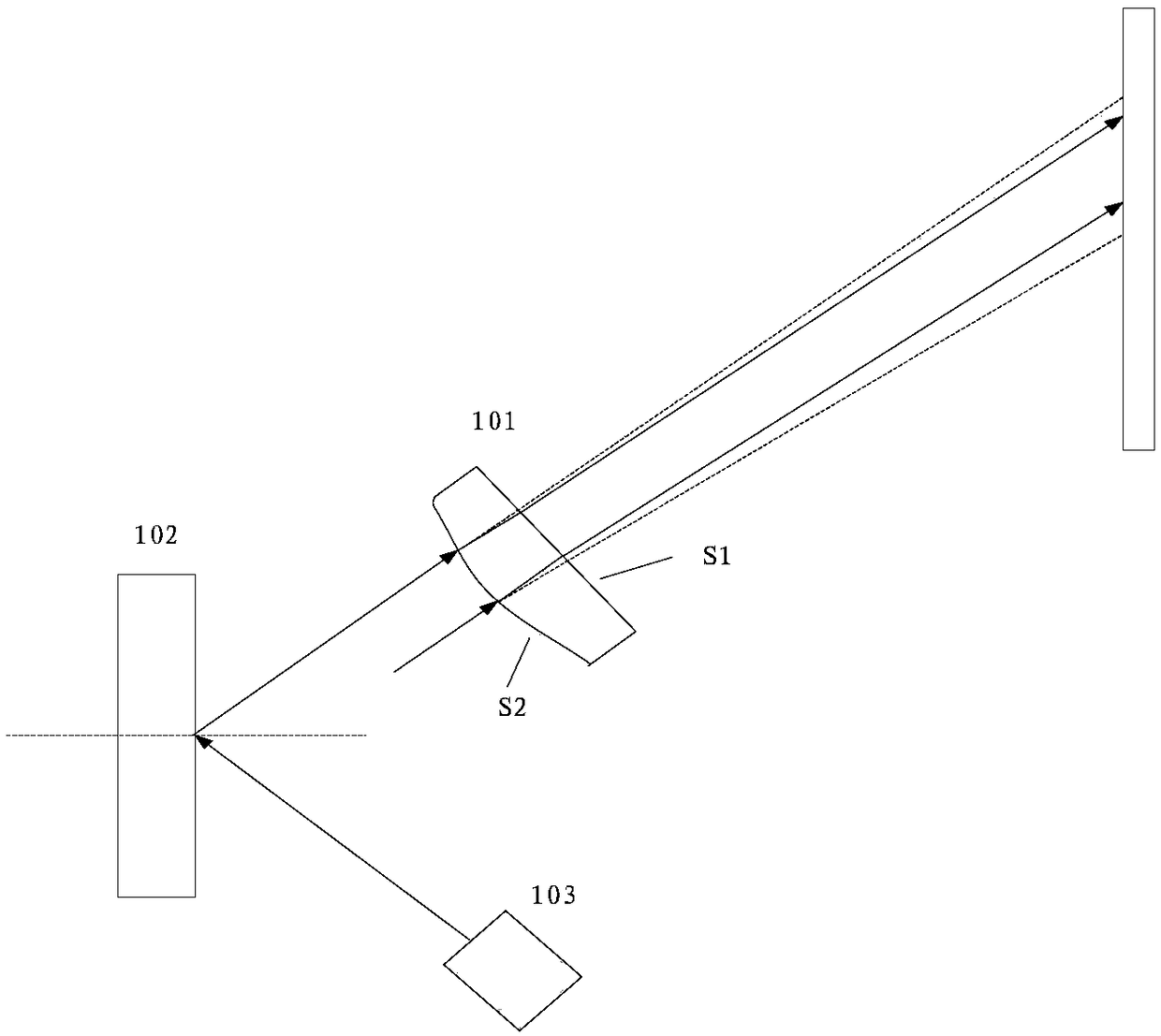
An embodiment of the present application provides a laser projection equipment, comprising a refractive lens, a MEMS mirror and a laser; Wherein the MEMS controls the MEMS mirror wobble based on a drive signal. The laser emits a laser beam to the MEMS mirror. The MEMS mirror reflects the laser beam to the refractive lens. The refractive lens refracts the laser beam to a screen. Wherein the curvature variation law of the refractive lens at different positions from the first end to the second end of the refractive lens in the horizontal direction conforms to a sinusoidal variation law, so that the laser beam is incident on different positions of the refractive lens in the horizontal direction with the MEMS mirror swinging to obtain different exit angles. A technical problem of image distortion due to change in that angular velocity of horizontal operation of the MEMS is solved by the present application.

Description

technical field [0001] The embodiments of the present application relate to the technical field of micro-projection, and in particular, to a laser projection device. Background technique [0002] At present, a laser beam scanning projector (Laser Beam Scanning, English abbreviation: LBS) has been widely used and developed due to its advantages of simple structure, small size, low power consumption, and no need for focusing. [0003] LBS consists of laser control system, laser, MEMS (Microelectromechanical Systems, MicroelectromechanicalSystems), scanning mirror control system and so on. The projection principle is that the laser control system controls the laser to emit laser light to the MEMS mirror according to the acquired image. Under the control of the driving signal generated by the scanning mirror control system, the MEMS mirror swings around the horizontal and vertical axes, so as to reflect the laser beam to the synthetic pixels on the screen to realize image displ...

Claims


Application Information

Patent Timeline
IPC IPC(8): G03B21/14H04N9/31
CPCH04N9/3161H04N9/3179G03B21/147
Inventor 高文刚
Owner GOERTEK OPTICAL TECH CO LTD
Learn More