
An antenna system of a reconfigurable radiation mode

An antenna system and radiation pattern technology, applied in the field of the Internet of Things, can solve the problems of limited connection distance, increase system cost, increase the insertion loss of antenna directivity scheme, etc., and achieve the effect of extending communication distance, saving system cost and low cost.

Active Publication Date: 2018-12-11
CHINA HYDROELECTRIC ENGINEERING CONSULTING GROUP CHENGDU RESEARCH HYDROELECTRIC INVESTIGATION DESIGN AND INSTITUTE
View PDF15 Cites 1 Cited by
  • Summary
  • Abstract
  • Description
  • Claims
  • Application Information

AI Technical Summary

Problems solved by technology

[0004] The technical problem to be solved by the present invention is to propose an antenna system with a reconfigurable radiation pattern to solve the problem that the traditional Internet of Things antenna system adopts the omnidirectional radiation pattern and the connection distance is limited, while the beamforming technology is used to increase the antenna directivity. The problem of introducing additional insertion loss and increasing system cost

Method used


Image

  • An antenna system of a reconfigurable radiation mode
  • An antenna system of a reconfigurable radiation mode
  • An antenna system of a reconfigurable radiation mode

Examples


Embodiment

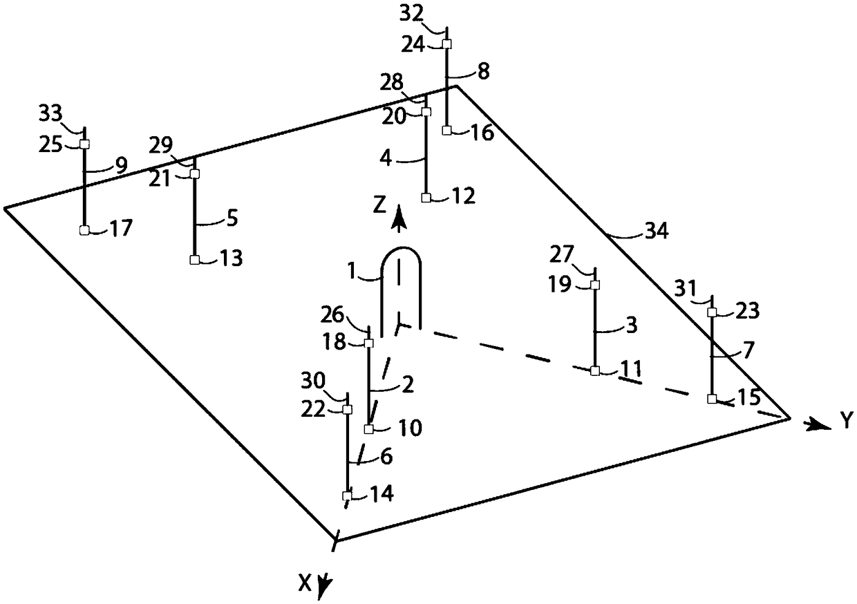
[0028] like figure 1 As shown, in this embodiment, both the driving element 1 and the parasitic element are located on the ground plane 34, the driving element 1 is located at the center of the square ground plane 34, and the parasitic elements are distributed around the driving element; wherein the driving element 1 adopts a folded dipole antenna, Using the folded dipole antenna as the driving element 1 has the advantages of high gain, wide frequency coverage and low noise.

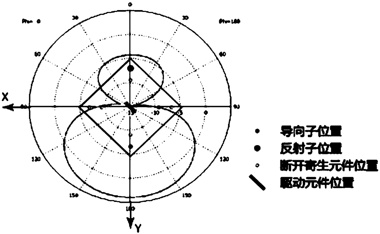
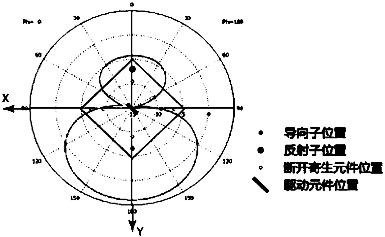
[0029] In order to take both gain and cost into account, there are two groups of parasitic elements in this embodiment, and considering the characteristics of electromagnetic wave transmission and reflection in space, in order to reduce noise interference and energy loss and obtain the maximum gain, the two groups of parasitic elements are arranged in a front-rear correspondence Set on the diagonal of the square ground plane 1, the distance from the driving element 1 to the first group of parasitic eleme...


PUM


Abstract

The invention relates to an antenna system configuration technology in the field of Internet of things, and discloses an antenna system of areconfigurable radiation mode, which solves the problem thatthe connecting distance of the traditional Internet of Things antenna system is limited by adopting the omni-directional radiation modewhile external insertion loss is introduced and system cost is increased in a scheme by adopting a beamforming technology for increasing the antenna directionness. The antenna system includes a set of drive elements and parasitic elements located on a ground plane; The parasitic element group comprises parasitic elements distributed around the driving elements, and each parasitic element is composed of upper and lower parts, and the upper and lower parts and the lower part and the ground plane are connected with controllable switches. The invention is applicable to scenarios in which a wireless system needs to be arranged in the field of the Internet of Things.

Description

technical field [0001] The invention relates to an antenna system configuration technology in the field of the Internet of Things, in particular to an antenna system with a reconfigurable radiation pattern. Background technique [0002] With the development of the technology of the Internet of Things, more and more networked devices are integrated into the daily production activities of society. Compared with wired communication, wireless communication is more favored by users in the field of Internet of Things due to its advantages of no need for wiring and convenient networking. [0003] Currently, omnidirectional antennas (such as monopole antennas) are the most common antenna solution for most IoT wireless systems. The omnidirectional radiation pattern of this antenna limits the connection distance of the entire IoT system. Another option for IoT wireless systems is to increase the transmission distance by using beamforming techniques in array antennas to increase the ...

Claims


Application Information

Patent Timeline
Patent Type & Authority Applications(China)
IPC IPC(8): H01Q21/29H01Q1/36H01Q3/44H01Q9/14H01Q9/26
CPCH01Q1/36H01Q3/446H01Q9/145H01Q9/26H01Q21/29
Inventor 王仁坤邱向东柳影丁旭阳陈万涛张志伟
Owner CHINA HYDROELECTRIC ENGINEERING CONSULTING GROUP CHENGDU RESEARCH HYDROELECTRIC INVESTIGATION DESIGN AND INSTITUTE
Learn More