

A purifier and a purification method thereof
A purifier and purification device technology, applied in chemical instruments and methods, separation methods, filtration separation and other directions, can solve the problem of high purification cost, achieve effective filtration effect, improve filtration effect, and improve the effect of moving path
- Summary
- Abstract
- Description
- Claims
- Application Information
AI Technical Summary
Problems solved by technology
Method used
Image

Examples
Embodiment 1
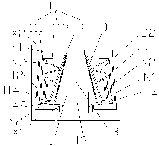
[0084] like figure 1 The air purifier described above is provided with a base X1, an isolation net cover X2 and a purification main body; the purification main body includes an upper cover plate Y1, a lower cover plate Y2, a hollow filter round table 10, a filter air dissolving pool 11, an air outlet Hollow round table 12, motor 13 and ultrasonic generator 14; Described hollow filter round table 10, filter gas dissolving tank 11, air outlet hollow round table 12 are placed on the motor 13 from inside to outside in turn; The output shaft 131 of described motor 13 is fixed On the upper cover plate Y1, the motor 13 can drive the upper cover plate Y1 to rotate, and the smaller diameter end of the hollow filter round table 10, the filter gas dissolving pool 11, and the air outlet hollow round table 12 is all fixed on the upper cover plate; The cover plate Y2 is rotatably set on the motor 13, and the larger diameter end of the hollow filter round table 10, the filter gas dissolving...
Embodiment 2
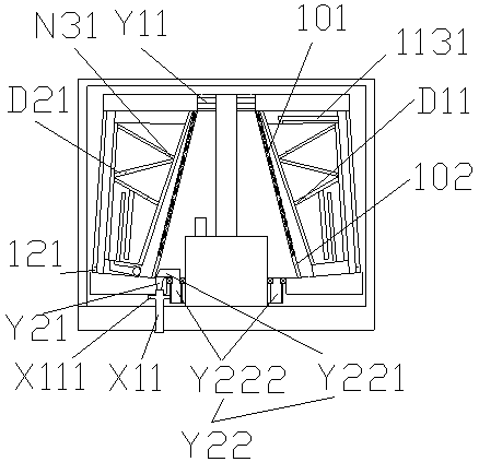
[0115] like Figure 7 , 8 As shown, the particle discharge system described in embodiment 1 can also adopt the following scheme:
[0116] The particle sewage section 102' is located at the end of the hollow filter round table 10' abutting the lower cover plate Y2'; the end of the particle sewage section 102' is located at the end of the lower cover plate Y2', from point C to point D , the diameter gradually becomes larger in the clockwise direction; the sewage outlet of the particle sewage section 102' is located between point C and point D; the normals of point C and point D are on the same straight line.
[0117] A piston M is arranged in the discharge pipe, and the dirt in the discharge pipe X11' is sucked out by pulling the piston M during discharge.
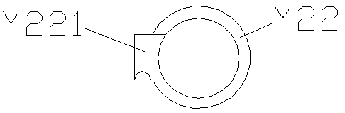
[0118] Working principle: Through the above analysis, during the high-speed rotation of the particle sewage section 102', all the particles will be concentrated in the sewage hole Y22' between points C and D.
Embodiment 3
[0120] like Figure 13 As shown, the gas separation system described in Embodiment 1 can also adopt the following scheme:
[0121] The dissolving tank R is provided with one or more horizontal partitions, and the liquid level of the solvent in the dissolving tank R is at least higher than one horizontal partition; in this embodiment, there are five horizontal partitions R31, R32, R33, R34, and R35. Separators, each horizontal partition is provided with air outlets, and the liquid level of the solvent is above R31; the air outlets are all arranged on one side of the corresponding horizontal board, and the air outlets of two adjacent horizontal partitions are distributed on On the other hand, in this embodiment, the air outlet R21 of R31 is distributed on the right side of R31, the air outlet R22 of R32 is distributed on the left side of R32, the air outlet R23 of R33 is distributed on the right side of R33, and the outlet of R34 The air hole R24 is distributed on the left side...
PUM
 Abstract
Description
Claims
Application Information