Boat pushing reducing furnace device and gas supply method

A reduction furnace and furnace tube technology, which is applied in the field of powder metallurgy, can solve the problems that hydrogen cannot enter the recovery system, the operation of the recovery system is interrupted, and the size of the furnace tube is large, so as to reduce safety hazards, reduce overflow loss, and improve utilization.

Active Publication Date: 2018-12-14
北京钢研新冶工程技术中心有限公司
View PDF7 Cites 2 Cited by
  • Summary
  • Abstract
  • Description
  • Claims
  • Application Information

AI Technical Summary

Problems solved by technology

However, these patents are limited to the treatment of hydrogen, and do not involve the hydrogen intake system and return gas system of the reduction furnace itself, and these patented technologies are all for the recovery of hydrogen in the tungsten powder and molybdenum powder industries, that is, in the multi-tube furnace Hydrogen recovery is realized on the multi-tube furnace, and hydrogen recovery is easy to realize on the multi-tube furnace because each furnace door in the multi-tube furnace is opened in turn, that is to say, only one furnace door is opened at the same time, and because the multi-tube furnace has many furnace tubes, Opening a furnace door has almost no effect on the total intake hydrogen flow and return hydrogen flow, but for single-tube furnaces, double-tube furnaces and four-tube furnaces, it is very different from multi-tube furnaces, and the size of the furnace tubes Larger, that is, when the furnace door is opened, hydrogen overflows from the furnace mouth, resulting in a large loss of hydrogen, the pressure difference between the furnace tube and the atmospheric pressure is almost zero or unstable, and hydrogen cannot enter the recovery system, resulting in the interruption of the recovery system

Method used


Image

  • Boat pushing reducing furnace device and gas supply method

Examples


Embodiment 1

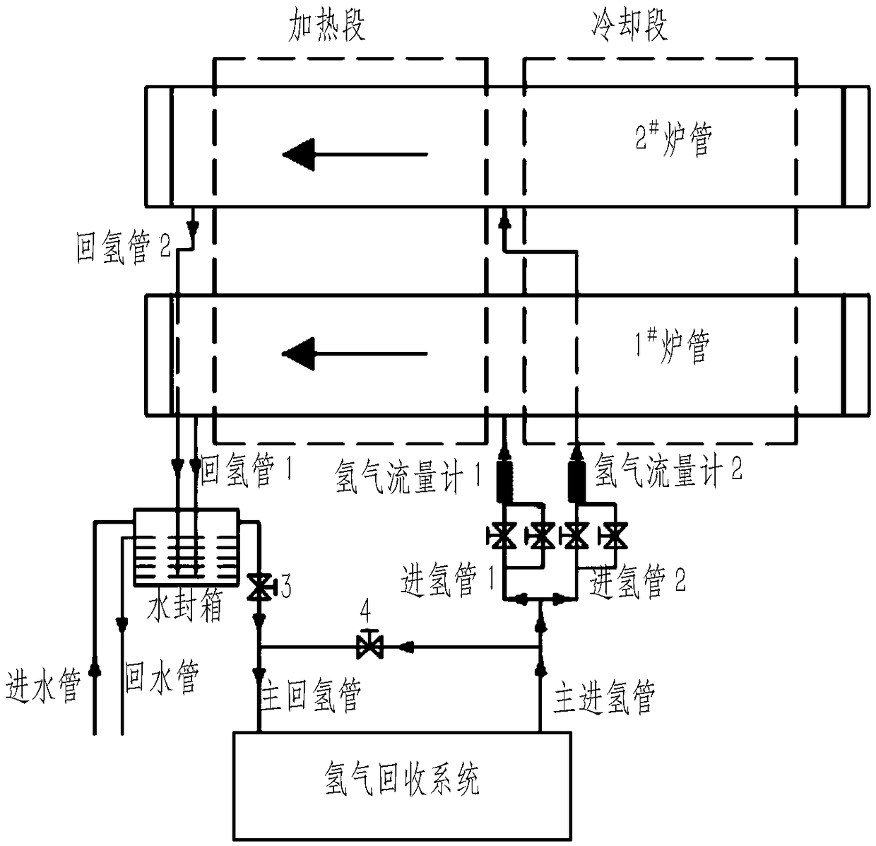
[0024] A specific embodiment of the present invention, such as figure 1 As shown, the reduction furnace is a double-tube pusher reduction furnace for production, including furnace tubes, hydrogen inlet pipelines, hydrogen return pipelines and water-sealed boxes. Furnace tube includes 1 # furnace tube and 2 # The furnace tube, the hydrogen inlet pipeline includes the main hydrogen inlet pipe, the hydrogen inlet pipe 1 and the hydrogen inlet pipe 2, the hydrogen return pipeline includes the main hydrogen return pipe, the hydrogen return pipe 1 and the hydrogen return pipe 2, and the water seal box is equipped with Water pipes and return pipes. The hydrogen inlet pipe 1 is provided with a solenoid valve 1-1 and a bypass valve 1-2, and the hydrogen inlet pipe 2 is provided with a solenoid valve 2-1 and a bypass valve 2-2. The solenoid valve is a kind of program control valve, and the bypass valve The valve is a normally open valve. A solenoid valve 3 is provided on the main hy...

Embodiment 2

[0027] The hydrogen in the hydrogen storage tank (tank D) enters the furnace tube through the hydrogen inlet pipeline, and the oxidized metal powder is reduced in the furnace tube, then the hydrogen passes through the water-sealed box, and enters the hydrogen recovery system through the main hydrogen return pipe.

[0028] Gas supply method 1 for the push boat reduction furnace: When the reduction furnace is not in operation, that is, when the furnace door is closed, the leakage of hydrogen gas is very small and can be ignored due to the good sealing of the push boat reduction furnace. Except for a small part of the hydrogen consumption (about 10%), most of the hydrogen enters the hydrogen recovery system through the hydrogen return pipeline.

[0029] When 1 # furnace tube and 2 # When the furnace doors of the furnace tube are all closed, the solenoid valve 1-1, the solenoid valve 2-1 and the solenoid valve 3 are all in the open state, the solenoid valve 4 is in the closed sta...

Embodiment 3

[0031] The second method of gas supply to the push boat reduction furnace: When 1 # furnace tube or 2 # When one of the furnace doors of the furnace tube is opened to feed materials, the corresponding solenoid valve 1-1 or solenoid valve 2-1 is automatically closed, solenoid valve 3 is open, solenoid valve 4 is closed, bypass valve 1-2 and bypass valve The through valve 2-2 is a normally open valve; when the furnace door is closed, the corresponding solenoid valve is automatically opened.

[0032] When 1 # When the furnace tube is opened and fed, hydrogen overflows, then 1 # The pressure difference between the pressure at the inlet of the furnace tube and the atmosphere is almost zero, which makes 1 # The hydrogen in the furnace tube cannot enter the main hydrogen return pipe through the water seal. At this time, the solenoid valve 1-1 is automatically closed, and the hydrogen only passes through the bypass valve 1-2 at a distance of 5m. 3A small flow rate of / h flows into...


PUM


Abstract

The invention discloses a boat pushing reducing furnace device and a gas supply method and belongs to the technical field of powder metallurgy. The boat pushing reducing furnace device comprises furnace pipe hydrogen inlet pipelines and hydrogen return pipelines. The hydrogen inlet pipelines are provided with program control valves and bypass valves, and the bypass valves are normally-open valves.The hydrogen inlet pipelines comprise a first hydrogen inlet pipeline and a second hydrogen inlet pipeline. The first hydrogen inlet pipeline is provided with the first program control valve and thefirst bypass valve, and the second hydrogen inlet pipeline is provided with the second program control valve and the second bypass valve. A third program control valve is arranged on a main hydrogen return pipe, and a fourth program control valve is arranged between the hydrogen return pipelines and the hydrogen inlet pipelines. The gas supply method of the boat pushing reducing furnace device mainly comprises the step that the program control valves are controlled to be opened and closed. The problem that due to the fact that the barometric pressure of the interior of a furnace pipe and atmosphere is zero or unstable, and consequently a recovery system stops operating, and the recovery process cannot be smoothly carried out is solved, and hydrogen losses caused during blow-in feeding arereduced.

Description

technical field [0001] The invention belongs to the technical field of powder metallurgy, and in particular relates to a boat push reduction furnace device and a gas supply method. Background technique [0002] In the field of powder metallurgy, the use of hydrogen to reduce powder is a common process method. The hydrogen reduction method is not only an important powder manufacturing method, but also an important powder deep processing method. According to the number of furnace tubes, push boat type reduction furnaces are divided into single-tube, double-tube, four-tube and multi-tube push boat furnaces. Multi-tube furnaces include 14-tube furnaces, 18-tube furnaces, etc. The width (or diameter) of a single furnace tube in a multi-tube furnace is small, generally less than 200mm, while the furnace tubes in a single-tube, double-tube, and four-tube furnace are much wider, generally greater than 300mm. Multi-tube furnaces are generally used for the reduction of tungsten powde...

Claims


Application Information

Patent Timeline
Patent Type & Authority Applications(China)
IPC IPC(8): B22F9/22
CPCB22F9/22
Inventor 赵志民方建锋庞建明邸久海
Owner 北京钢研新冶工程技术中心有限公司
Why Eureka
Try Eureka