
Water quality detecting device

A water quality testing device and technology for water quality testing, applied in unloading devices, packaging, testing water, etc., can solve problems such as difficult outer wall protection, loose reagent bottles, affecting water quality testing efficiency, etc., to achieve low cost, reduce shaking, and improve stability. Effects of Sex and Safety

Active Publication Date: 2018-12-14
宜昌绿源饮品科技股份有限公司
View PDF4 Cites 8 Cited by
  • Summary
  • Abstract
  • Description
  • Claims
  • Application Information

AI Technical Summary

Problems solved by technology

[0003] A Chinese patent discloses a water quality detection device (authorized notification number CN207351996U). The water quality detection device, through the cooperation of a water storage bottle, a bracket and a splint, the water storage bottle contains a detection water sample, and the detection instrument can simply detect the detection water sample. If you want accurate test data, you need to take the test water sample back to the laboratory for all-round testing. The splint and bracket clamp the water storage bottle to prevent the water storage bottles from colliding with each other and causing damage to the water storage bottle. The sponge pad has a buffer for the water storage bottle Function, it is convenient to bring the tested water samples back to the laboratory for all-round testing, which can meet the needs of users, but it is difficult for the water quality testing device to effectively protect its outer wall, and at the same time, it is easy to place the reagent bottles in the tank during the moving process. There is a problem of looseness, and the staff cannot take multiple reagent bottles at one time when testing, which affects the testing efficiency of water quality

Method used


Image

  • Water quality detecting device
  • Water quality detecting device
  • Water quality detecting device

Examples


Embodiment Construction

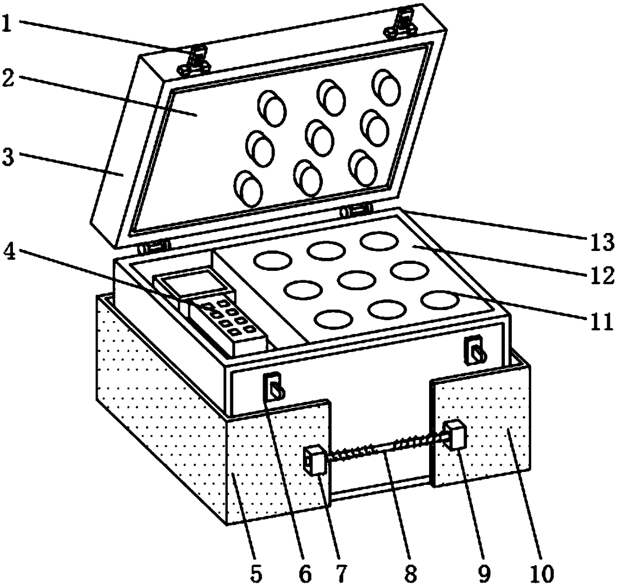
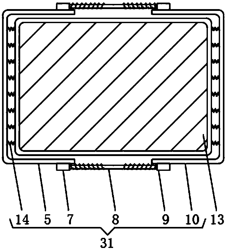
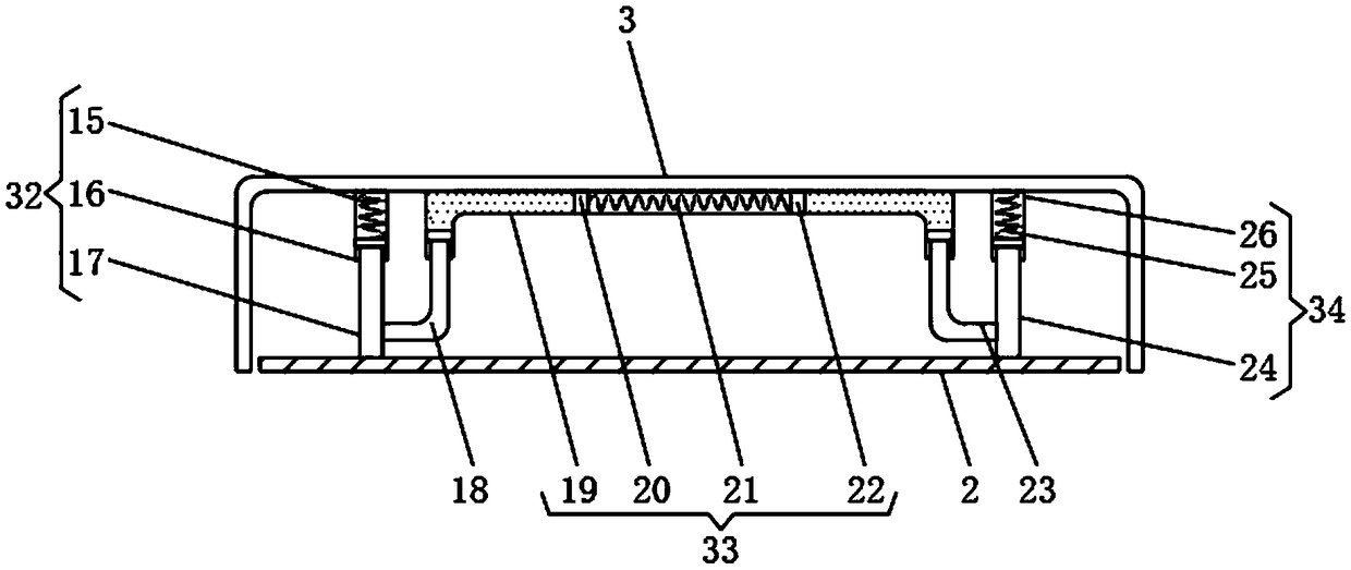
[0024] see Figure 1~4 , in an embodiment of the present invention, a water quality detection device includes a water quality detection box body 13, a protective cover 3 is connected to the top of the water quality detection box body 13 through a hinge rotation, and the outside of the water quality detection box body 13 is sleeved with a buffer adjustment Protection device 31, buffer adjustment protection device 31 comprises the first protective plate 5, the first fixed block 7, threaded rod 8, the second fixed block 9, the second protective plate 10 and the first buffer spring 14, one end thread of threaded rod 8 The first fixed block 7 is sleeved, and the other end of the threaded rod 8 is threaded with the second fixed block 9. The inner wall of the first fixed block 7 is provided with a forward thread groove, and the rear side of the first fixed block 7 The first protective plate 5 is fixedly installed, the inner wall of the second fixed block 9 is provided with a reverse ...


PUM


Abstract

The invention discloses a water quality detecting device. The water quality detecting device comprises a water quality detecting box body; the upper portion of the water quality detecting box body isrotationally connected with a protective cover through a hinge; the outer portion of the water quality detecting box body is sleeved with a buffer adjusting protection device; a placement frame is mounted in the water quality detecting box body; a placement groove is formed in the placement frame; and a pushing device is arranged on the side, close to a storage battery, of the lower portion of theplacement frame. By arranging the buffer adjusting protection device, the outer side wall of the water quality detecting box body can be effectively protected, damage of external force to the water quality detecting box body is reduced, through combined application of a first shock absorbing protection device, a second shock absorbing protection device and a third shock absorbing protection device, after a baffle makes contact with the placement groove, swinging of reagent bottles in the placement groove can be reduced, by arranging the pushing device, the reagent bottles in the placement groove can be pushed out, and staff can conduct relative detection on the different reagent bottles conveniently.

Description

technical field [0001] The invention relates to the technical field of water quality detection boxes, in particular to a water quality detection device. Background technique [0002] Water is the source of life. Human beings cannot do without water in life and production activities. The quality of drinking water is closely related to human health. With the development of social economy, scientific progress and the improvement of people's living standards, people's drinking Water quality requirements continue to increase, and drinking water quality standards are also continuously developed and improved accordingly. Due to the formulation of drinking water quality standards and people's living habits, culture, economic conditions, scientific and technological development levels, water resources and their water quality status, etc. Many factors are related. Not only between countries, but also between different regions of the same country, there are differences in the requireme...

Claims


Application Information

Patent Timeline
Patent Type & Authority Applications(China)
IPC IPC(8): B65D25/10B65D25/02B65D25/38B65D43/16B65D81/02G01N33/18
CPCB65D25/02B65D25/107B65D25/38B65D43/164B65D81/05G01N33/18
Inventor 车国容
Owner 宜昌绿源饮品科技股份有限公司
Learn More