Infrared optical material impurity test method

A technology of infrared optical materials and testing methods, applied in the field of optical material impurity testing, can solve problems such as shortening testing time, and achieve the effects of reducing costs, real testing results, and fast testing

Active Publication Date: 2020-09-08
CHINA NORTH STANDARDIZATION CENT
View PDF6 Cites 0 Cited by
  • Summary
  • Abstract
  • Description
  • Claims
  • Application Information

AI Technical Summary

Problems solved by technology

[0007] The technical problem to be solved by the present invention is: how to design a testing principle and method for impurities in infrared optical materials, so as to solve the actual testable problems of impurities in optical materials, reduce the complexity of the composition of the testing device and the testing process, and obtain materials that meet the requirements of impurities in materials. Real-world results, lower test costs, shorter test times

Method used


Image

  • Infrared optical material impurity test method
  • Infrared optical material impurity test method
  • Infrared optical material impurity test method

Examples


Embodiment Construction

[0042] In order to make the purpose, content and advantages of the present invention clearer, the specific implementation manners of the present invention will be further described in detail below in conjunction with the accompanying drawings and embodiments.

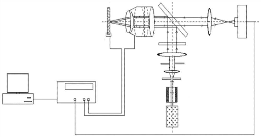
[0043] The inventors of the present invention found that the impurities in the infrared optical material can be imaged once by using the depth of field of the infrared camera system, and the actual possession of impurities in the optical material can be obtained comprehensively, so that the impurity test of the infrared optical material is simplified and real . The proposal of this invention is based on two basic points, one is to have a deep understanding of the characteristics and performance relationship of the optical system imaging (the performance relationship of the optical system is mainly the relationship between resolution, depth of field, F number, etc.), and the other is Have a deep understanding of the actu...


PUM

PropertyMeasurementUnit
thicknessaaaaaaaaaa

Abstract

The invention relates to an infrared optical material impurity testing method, and relates to the technical field of optical material impurity testing. According to the method, based on the depth field characteristic and the scene imaging principle of an infrared photographing system, the condition of the impurities in the infrared material which is not transparent to the visible light is subjected to primary imaging of the depth field range of the infrared photographing system to obtain all the impurity conditions inside the infrared optical material; the method for testing the impurities inside the infrared material which is not transparent in visible light is simple in equipment requirement, and a precise platform for carrying out two-dimensional automatic movement of a sample and a precise one-dimensional automatic moving platform for carrying a microscope objective lens are not needed, so that the cost of the testing equipment is lowered; the test method is carried out by real imaging through one time of camera shooting, without processing of an overlapped imaging result, so that the reflected test result is true; and the testing method can be completed by one time of camera shooting, so that the test is quick and convenient and short in time.

Description

technical field [0001] The invention relates to the technical field of optical material impurity testing, in particular to an infrared optical material impurity testing method. Background technique [0002] Impurities in optical materials are non-uniform material defects such as air bubbles and stones left after the manufacture of optical materials. These non-uniform material defects will seriously affect the imaging quality of the optical system. Testing the impurities in optical materials is a necessary link to evaluate whether optical materials can meet the requirements of use. For optical materials in the visible band, the impurities in the material are irradiated by a diffuse reflection light source, and the number and size of impurities are recorded by direct observation with a magnifying glass, and then brought into the formula to calculate and evaluate the level of impurities in optical materials. [0003] For infrared optical materials (wavelength 0.8 μm ~ 14 μm) t...

Claims


Application Information

Patent Timeline
Patent Type & Authority Patents(China)
IPC IPC(8): G01N21/35G01N21/359
CPCG01N21/35
Inventor 麦绿波
Owner CHINA NORTH STANDARDIZATION CENT
Why Eureka
Try Eureka