Eureka AIR delivers breakthrough ideas for toughest innovation challenges, trusted by R&D personnel around the world.

Earth gas light suppression method and system for synchronous band target optical observation satellite

A technology for observing satellites and synchronous belts, which is applied in the field of astronautical starry sky detection, and can solve the problems of high technical difficulty and cost of stray light suppression of ultra-high sensitivity space cameras, complex observation mission planning of observation satellites, and increased workload of satellite operation control management. , to achieve the effect of reducing the workload of satellite operation control management, improving the observation efficiency, and improving the suppression effect.

Active Publication Date: 2018-12-14
SHANGHAI ENG CENT FOR MICROSATELLITES
View PDF7 Cites 6 Cited by
  • Summary
  • Abstract
  • Description
  • Claims
  • Application Information

AI Technical Summary

Problems solved by technology

[0004] The traditional method can improve the earth, atmosphere and light suppression ability of the space observation camera at an integrated level, but the cost is high and the technology is difficult, especially the stray light suppression technology for ultra-high sensitivity space cameras is difficult and costly
In addition, because the arc section affected by the earth, atmosphere and light changes with the seasons, the observation task planning of the observation satellite is complicated, and the workload of satellite operation and control management becomes larger.

Method used


Image

  • Earth gas light suppression method and system for synchronous band target optical observation satellite
  • Earth gas light suppression method and system for synchronous band target optical observation satellite
  • Earth gas light suppression method and system for synchronous band target optical observation satellite

Examples


Embodiment Construction

[0037] The application relates to an earth-atmosphere-light suppression system for a synchronous zone target optical observation satellite, and a method for earth-atmosphere light suppression for a synchronous zone target optical observation satellite.

[0038] Terms such as "module" and "system" used in this application are intended to include computer-related entities such as, but not limited to, hardware, firmware, combination of hardware and software, software, or software in execution. For example, a module may be, but is not limited to being, a process running on a processor, a processor, an object, an executable, a thread of execution, a program, and / or a computer. For example, both an application running on a computing device and the computing device could be a module. One or more modules can reside within a process and / or thread of execution.

[0039] The terms "comprising", "comprising", "having" and their derivatives do not exclude the existence of any other compon...


PUM


Abstract

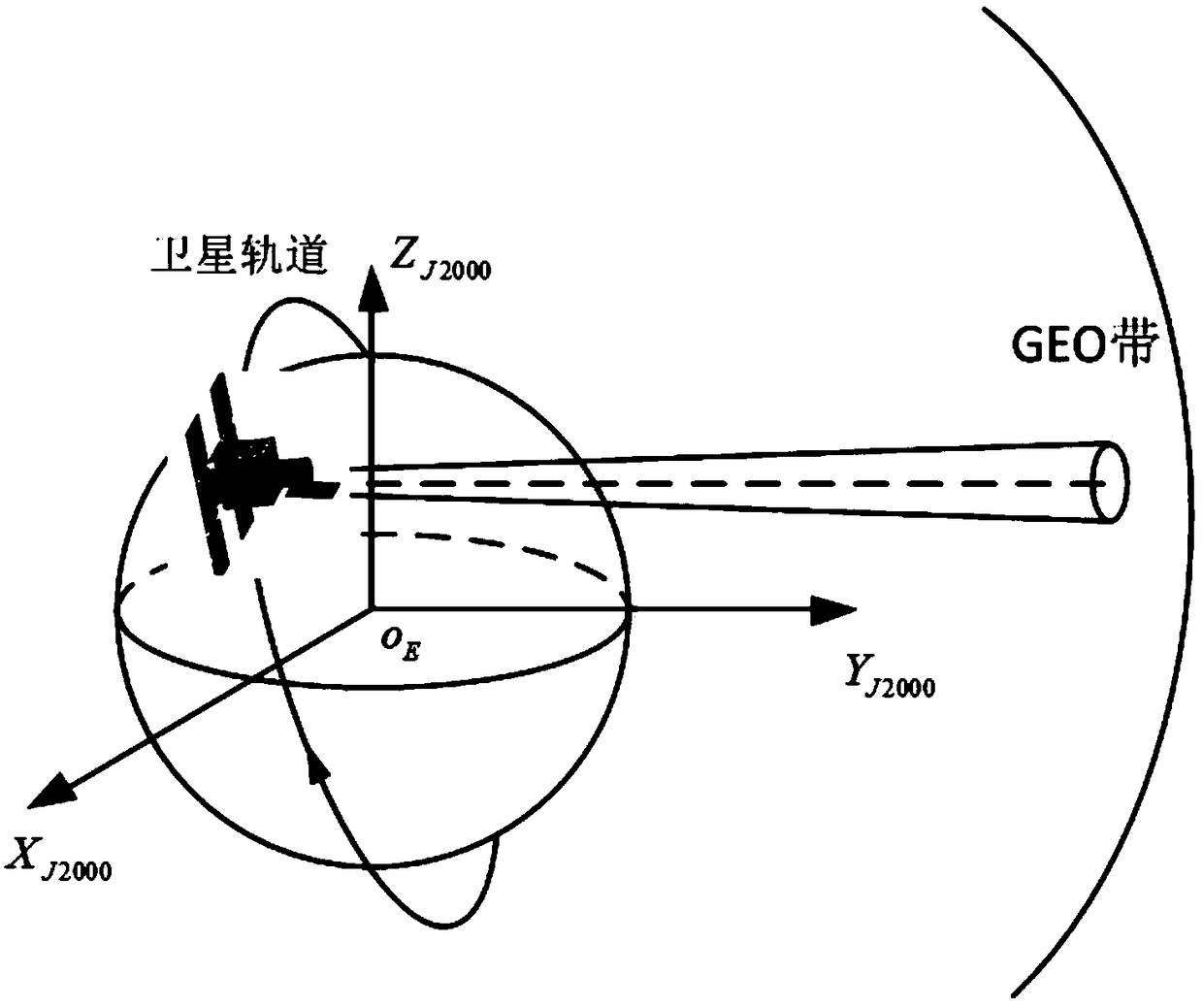
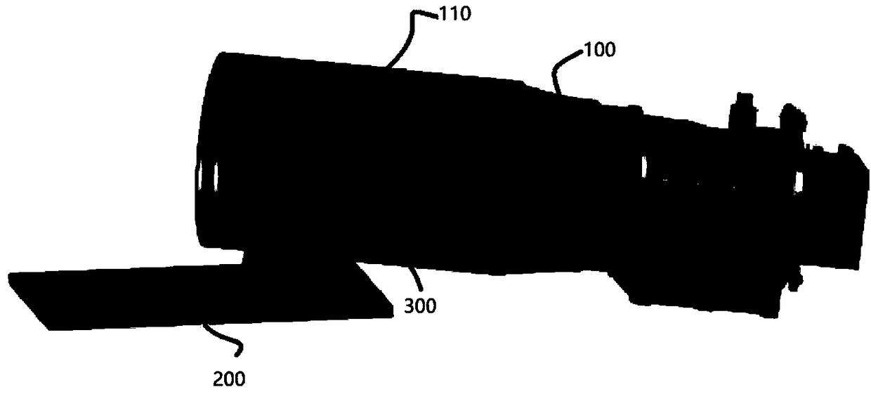
The application relates to an earth gas light suppression method and system for a synchronous band target optical observation satellite. The system includes a satellite, an optical observation moduleand a baffle, wherein the orbit of the satellite selects a dawn-dusk sun-synchronous orbit, and maintains the attitude to be earth-oriented; the optical observation module is installed on the satellite and is perpendicular to the main axis of the satellite; and the baffle is installed on the optical observation module, and during the operation of the satellite, the baffle is arranged between the optical observation module and a ground plane, wherein the satellite is operated according to an attitude maneuver rule model to achieve the traversal observation of latitudes that need to be stared. By adopting the technical scheme of the application, the suppression of the earth gas light can be realized only through a simple structural design, and the operation is simple and the cost is saved.

Description

technical field [0001] The present application relates to the field of space exploration, in particular to a method and system for suppressing earth, atmosphere and light of a synchronous belt target optical observation satellite. Background technique [0002] For the field of aerospace-like starry space exploration, the use of space optical observation systems for detection has many advantages such as flexible maneuverability, light observation range, long running time, short data update cycle, and high observation accuracy. [0003] At present, the main means of suppressing atmospheric light by synchronous belt optical observation satellites are as follows: First, the stray light entering the system is suppressed by means of extinction measures such as apertures, inner / outer hoods, and light blocking rings. For example, the geoatmospheric light suppression methods adopted by the US space-based visible light telescope SBV and the Canadian space-based space target observatio...

Claims


Application Information

Patent Timeline
Patent Type & Authority Applications(China)
IPC IPC(8): G01S19/08G01C21/24
CPCG01W1/08G01S19/42G01S19/21Y02E10/10
Inventor 朱永生胡海鹰郑珍珍李灏陆欢欢雷广智
Owner SHANGHAI ENG CENT FOR MICROSATELLITES
Why Eureka
Eureka Blog
Learn More