
A temperature field analysis method of an engine exhaust manifold considering heat radiation

An exhaust manifold and engine technology, applied in computer-aided design, special data processing applications, instruments, etc., can solve the problems of exhaust manifold high heat load, exhaust manifold crack failure, large temperature gradient, etc., to achieve shortening Computation time, precise 1D thermodynamic boundary conditions, effects of improved accuracy

Active Publication Date: 2018-12-14
ANHUI JIANGHUAI NAVISTAR DIESEL ENGINE CO LTD
View PDF2 Cites 3 Cited by
  • Summary
  • Abstract
  • Description
  • Claims
  • Application Information

AI Technical Summary

Problems solved by technology

[0002] As the environmental protection agencies of developed countries in the world have successively formulated and issued strict internal combustion engine emission regulations and fuel economy indicators, internal combustion engines with light weight, high power density and low emissions will become mainstream development products in the future. However, in order to realize internal combustion engines Higher power output and the catalytic conversion efficiency of the SCR selective catalytic reduction system will inevitably lead to a sharp increase in the heat load of the exhaust manifold, which may cause cracking failure of the exhaust manifold and melting of the valve chamber cover due to heat radiation The problem
[0003] Exhaust manifolds usually have to withstand extremely high heat loads, because the inner wall of the exhaust manifold is in direct contact with the high-temperature exhaust gas, and the exhaust manifold can only exchange heat through the cylinder head heat conduction, heat radiation and air convection. cooling method, which may lead to a large temperature gradient in the local position of the exhaust manifold and the maximum temperature exceeds the limit that the material can withstand

Method used


Image

  • A temperature field analysis method of an engine exhaust manifold considering heat radiation

Examples


Embodiment Construction

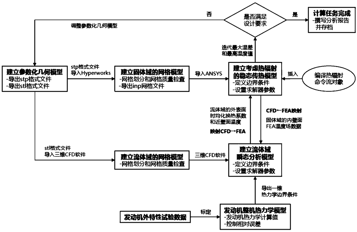
[0028] In this embodiment, a temperature field analysis method of an engine exhaust manifold considering heat radiation, such as figure 1 As shown, it mainly includes the following steps: 1. Utilize CAD modeling software to create the parametric geometric models of the solid domain and the fluid domain, and export the stp format file of the parametric geometric model of the solid domain and the parametric geometric model of the fluid domain respectively stl format file; 2. Establish the grid model of the solid domain and the fluid domain, and export the inp grid file of the solid domain; 3. Establish the thermodynamic model of the engine, and control the comparison between the engine thermodynamic calculation value and the engine external characteristic test data Error; 4. Define thermal boundary conditions for convective heat transfer and heat radiation; 5. Perform indirect coupled iterative calculations of solid and fluid domains. If the design requirements are not met, adjus...


PUM


Abstract

The invention discloses a temperature field analysis method of an engine exhaust manifold considering heat radiation, which comprises the following steps: 1, creating a parameterized geometric modelsof a solid domain and a fluid domain by using CAD modeling software; 2. establishing the mesh models of solid and fluid domains; 3, establishing the thermodynamic model of the engine and controlling the relative error between the thermodynamic calculation value of the engine and the external characteristic t data of the engine; 4. defining the thermal boundary conditions of convective heat transfer and thermal radiation; 5, performing the indirect coupling iterative computation of the solid domain and the fluid domain. The invention can compensate for the difficulty of directly evaluating thetemperature field distribution and the heat radiation level of the exhaust manifold in the design process of the exhaust manifold and the valve chamber cover, and solve the problems of cracking failure of the exhaust manifold and melting of the valve chamber cover due to the heat radiation.

Description

technical field [0001] The invention relates to the technical field of internal combustion engine exhaust systems, in particular to a method for analyzing the temperature field of an engine exhaust manifold considering heat radiation. Background technique [0002] As the environmental protection agencies of developed countries in the world have successively formulated and issued strict internal combustion engine emission regulations and fuel economy indicators, internal combustion engines with light weight, high power density and low emissions will become mainstream development products in the future. However, in order to realize internal combustion engines Higher power output and the catalytic conversion efficiency of the SCR selective catalytic reduction system will inevitably lead to a sharp increase in the heat load of the exhaust manifold, which may cause cracking failure of the exhaust manifold and melting of the valve chamber cover due to heat radiation The problem. ...

Claims


Application Information

Patent Timeline
IPC IPC(8): G06F17/50
CPCG06F2119/08G06F30/23Y02T90/00
Inventor 何常明朱文军
Owner ANHUI JIANGHUAI NAVISTAR DIESEL ENGINE CO LTD
Learn More