Training shoe gluing device

A gluing device and workbench technology, applied in footwear, gluing shoe parts, shoe-making machinery, etc., can solve problems such as poor bonding effect and uneven glue application, so as to avoid contact and stabilize the amount of glue output , the effect of reducing glue waste

Inactive Publication Date: 2020-06-02
CHONGQING HUIMEI IND CO LTD
View PDF5 Cites 0 Cited by
  • Summary
  • Abstract
  • Description
  • Claims
  • Application Information

AI Technical Summary

Problems solved by technology

[0004] The present invention intends to provide a gluing device for training shoes to solve the problems of uneven glue smearing and poor bonding effect caused by manual bonding of existing training shoes

Method used


Image

  • Training shoe gluing device
  • Training shoe gluing device
  • Training shoe gluing device

Examples


Embodiment

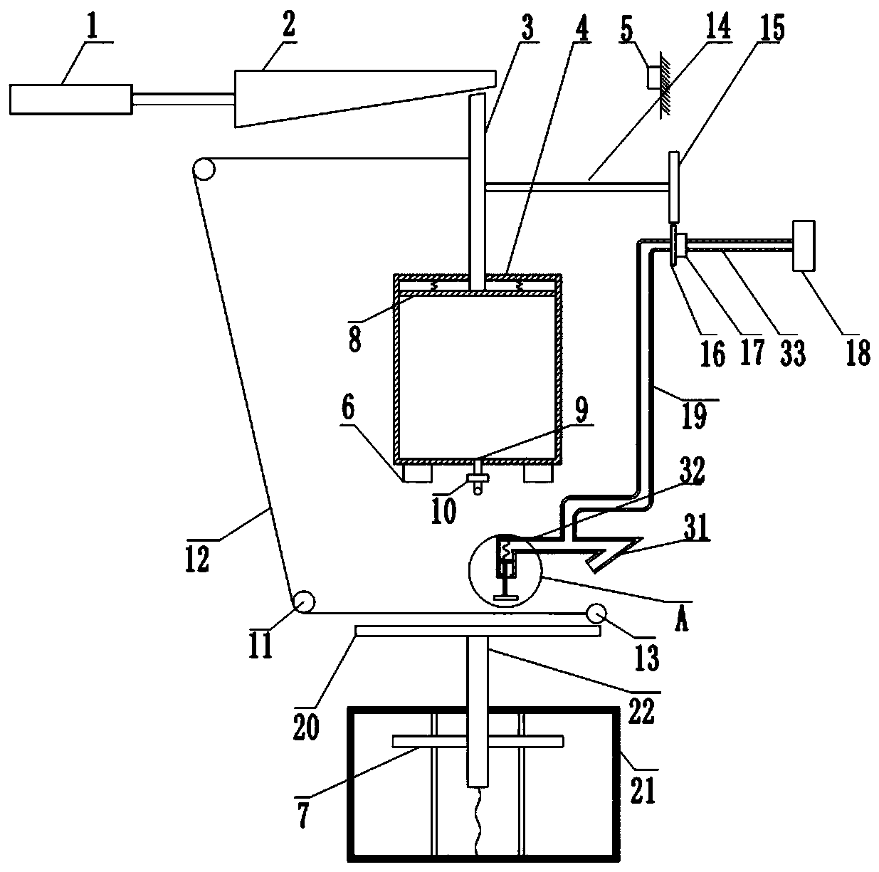
[0025] A kind of training shoes gluing device, such as figure 1 As shown, including a frame, the frame is fixed with a cylinder 1, a glue tank 4, a workbench 20 and a workbox 21 in order from top to bottom, and the upper surface of the workbench 20 is provided with a clamping groove capable of fixing the sole, and the size of the clamping groove is The same size as the sole, when the sole is placed in the groove, the bottom surface of the sole is flush with the upper surface of the workbench 20, the right side of the cylinder 1 is provided with a wedge block 2 that is horizontally slidably connected with the frame, and the piston rod of the cylinder 1 is connected to the wedge block. 2 welding, the right side of the wedge block 2 is provided with the first button switch 5 fixed on the frame, the button switch in the present embodiment is a normally closed switch, the first piston plate 8 is vertically slidably connected in the glue tank 4, An elastic member is welded between t...

specific Embodiment approach

[0031] The shoes that need to be glued are fixed in the clip groove on the workbench 20, and the soles are upward. Initially, the circuit of the button switch is turned on, and the first electromagnet 6 is energized to generate a magnetic field, which attracts the first magnet block 7 . Start the cylinder 1, and the piston rod drives the wedge block 2 to move laterally to the right, thereby exerting a downward pressure on the wedge rod 3, driving the wedge rod 3 to move down, so that the first piston plate 8 slides downward in the glue tank 4, The space pressure of the glue tank 4 below the first piston plate 8 is increased, the glue is extruded from the glue outlet 9, and falls on the fixed sole of the workbench 20, and the pull cord 12 is pulled while the wedge-shaped rod 3 slides, and the Rope 12 pulls cylinder 13 horizontally to the left, allowing glue to spread evenly on the sole.

[0032] When the wedge-shaped block 2 continues to move laterally to the right under the p...


PUM


Abstract

The invention relates to the field of shoe part bonding, and discloses a training shoe gluing device. The device comprises a rack and an air cylinder fixed to the rack, a piston rod of the air cylinder is coaxially connected with a wedge-shaped block which is in horizontal sliding connection with the rack, the rack is fixedly provided with a glue box and a workbench located below the glue box, andthe glue box is located on the lower side of the wedge-shaped block; a first piston plate is vertically and slidably connected with the interior of the glue box, and a wedge-shaped rod which is vertically and slidably connected with the rack is arranged between the first piston plate and the wedge-shaped block; the wedge-shaped rod is in sliding fit with the glue box, and an elastic piece is arranged between the upper surface of the first piston plate and the top wall of the inner side of the glue box; a glue outlet is formed in the bottom of the glue box, and a pressure valve is arranged atthe glue outlet; the rack is rotationally connected with a fixed pulley set, and the fixed pulley set comprises a first fixed pulley, a second fixed pulley and a pull rope; the rack is transversely and slidably connected with a roller between the glue box and the workbench, and the two ends of the pull rope are fixedly connected with the wedge-shaped rod and the roller respectively. According to the scheme, the device is used for gluing training shoes, and waste of glue can be reduced.

Description

technical field [0001] The invention relates to the field of gluing shoe parts, in particular to a gluing device for training shoes. Background technique [0002] Training shoes are a kind of rubber shoes, which basically include rubber soles and canvas shoes. Both rubber materials and canvas are wear-resistant materials, which are not only wear-resistant but also have good comfort. Therefore, training shoes have a wide range of promotion. In order to further improve the comfort of training shoes, air cushion insoles can be added to the soles of training shoes to improve the shock absorption capacity of training shoes and strengthen the protection of ankles and soles. [0003] In order to bond the air-cushioned insole and the sole together, the common method is manual bonding. Specifically: manually apply glue on the sole, then stick the air-cushioned insole to the sole, then press the two against each other, and use drying equipment to quickly solidify the glue for molding...

Claims


Application Information

Patent Timeline
Patent Type & Authority Patents(China)
IPC IPC(8): A43D25/18A43D25/20
CPCA43D25/18A43D25/20
Inventor 张素英
Owner CHONGQING HUIMEI IND CO LTD
Why Eureka
Try Eureka