
Mitral valve prosthesis, tricuspid valve prosthesis and stent thereof

一种二尖瓣瓣膜、三尖瓣瓣膜的技术,应用在医学假体领域,能够解决支架轴向窜动大、流出道阻塞、释放不当等问题,达到方便运动、容易调整、降低压迫和干涉的效果

Active Publication Date: 2018-12-18
SHANGHAI MICROPORT CARDIOFLOW MEDTECH CO LTD
View PDF17 Cites 3 Cited by
  • Summary
  • Abstract
  • Description
  • Claims
  • Application Information

AI Technical Summary

Problems solved by technology

[0004] Based on this, it is necessary to provide a mitral valve prosthesis, a tricuspid valve prosthesis, and a mitral valve prosthesis for the problem of the risk of obstruction of the outflow tract, and the large axial movement of the stent, which is difficult to locate and easily causes paravalvular leakage due to improper release. Valve prosthesis and its stent

Method used


Image

  • Mitral valve prosthesis, tricuspid valve prosthesis and stent thereof
  • Mitral valve prosthesis, tricuspid valve prosthesis and stent thereof
  • Mitral valve prosthesis, tricuspid valve prosthesis and stent thereof

Examples


Embodiment Construction

[0063] In order to facilitate the understanding of the present invention, the present invention will be described more fully below with reference to the associated drawings. A preferred embodiment of the invention is shown in the drawings. However, the present invention can be embodied in many different forms and is not limited to the embodiments described herein. Rather, these embodiments are provided so that the disclosure of the present invention will be thorough and complete.

[0064] Unless otherwise defined, all technical and scientific terms used herein have the same meaning as commonly understood by one of ordinary skill in the technical field of the invention. The terms used herein in the description of the present invention are for the purpose of describing specific embodiments only, and are not intended to limit the present invention. As used herein, the term "and / or" includes any and all combinations of one or more of the associated listed items.

[0065] Such a...


PUM


Abstract

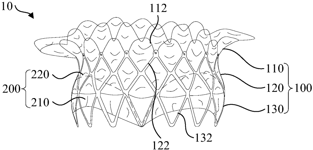
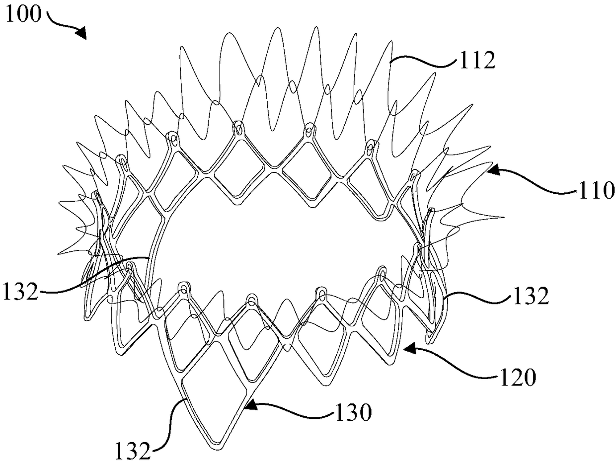
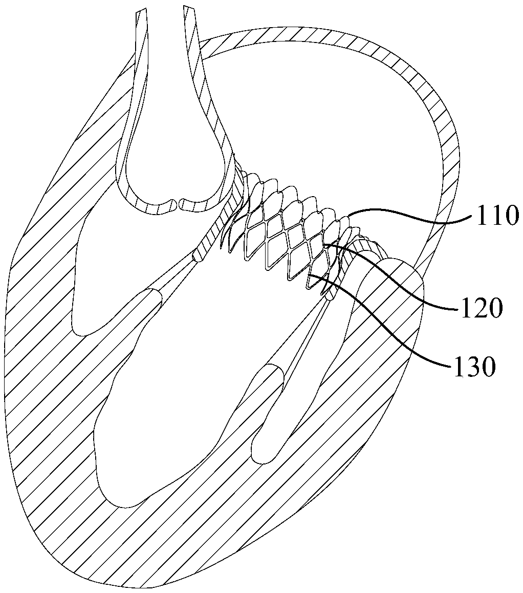
The invention relates to mitral valve prosthesis, tricuspid valve prosthesis and a stent thereof. The stent is used to support the heart valve of the mitral valve prosthesis; the stent has a contracted state for delivery and a deployed state for deployment; the stent comprises an inflow passage, a transition region and an outflow passage in the axial direction; two ends of the transition region are respectively connected with the inflow passage and the outflow passage; in the deployed state, the inflow passage is located upstream of the blood flow direction of the outflow passage, and the radial stiffness of the inflow passage is smaller than the radial stiffness of the outflow passage and / or the transition region. Because of the small radial stiffness of the inflow passage, the shape of the inflow passage is well adapted to the shape of the mitral annulus, which reduces the compression and interference of the aortic valve, and greatly reduces the risk of left ventricular outflow passage obstruction. During the release process, the shape of the inflow passage is easy to adjust to the change of the diameter of the stent, and the radial deformation and axial movement during the deployment of the stent can improve the release stability.

Description

technical field [0001] The invention relates to the technical field of medical prosthesis, in particular to a mitral valve prosthesis, a tricuspid valve prosthesis and a bracket thereof. Background technique [0002] The mitral valve, also known as the mitral valve, is located at the inflow of the left ventricle. The main structure is the mitral valve complex, including the mitral valve annulus, leaflets, chordae and papillary muscles. Some literatures also include the ventricular wall. The mitral annulus is the dense connective tissue around the left atrium ostium, and its anterior annulus is composed of part of the aortic valve annulus located in the left ventricular outflow tract, part of the left coronary annulus and the left and right fibrous triangles , the posterior annulus is the posterior leaflet attachment. The anterior leaflet of the mitral valve is a fibrous extension of the aortic valve, forming the left ventricular inflow tract with the posterior leaflet and c...

Claims


Application Information

Patent Timeline
Patent Type & Authority Applications(China)
IPC IPC(8): A61F2/24
CPCA61F2/2412A61F2/2418A61F2/2466A61F2230/0002A61F2250/0018A61F2250/0037A61F2250/0039A61F2250/0029A61F2/2436A61F2/2448
Inventor 赵春霞阳明陈国明刘明
Owner SHANGHAI MICROPORT CARDIOFLOW MEDTECH CO LTD
Learn More