Exhaust gas treatment device

A waste gas treatment device and waste gas technology are applied in the direction of combined devices, combustion methods, lighting and heating equipment, etc., which can solve the problems of inability to meet actual use requirements, single function, and low processing efficiency.

Inactive Publication Date: 2018-12-18
合肥名华教育科技有限公司
View PDF8 Cites 3 Cited by
  • Summary
  • Abstract
  • Description
  • Claims
  • Application Information

AI Technical Summary

Problems solved by technology

[0003] The traditional waste gas treatment system is not only complex in structure, large in size, high in cost and large in floor area, but also cannot be targeted at the particularity of the waste gas em

Method used


Image

  • Exhaust gas treatment device

Examples


Embodiment Construction

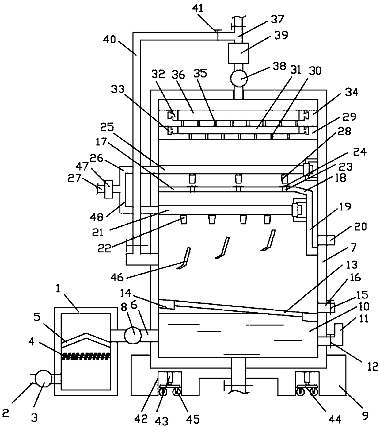
[0017] Such as figure 1As shown, an exhaust gas treatment device includes an exhaust gas pretreatment tank body 1, the lower end of the left side wall of the exhaust gas pretreatment tank body 1 is connected with an air inlet pipe 2, and the air inlet pipe 2 is connected with a first suction pump body 3, an electric heating tube 4 is horizontally connected between the middle parts of the left and right inner walls of the exhaust gas pretreatment tank body 1, and a pretreatment filter screen 5 is arranged on the upper side of the electric heating tube 4, and the pretreatment filter screen The outer edges of 5 are respectively fixed on the inner side wall of the exhaust gas pretreatment tank body 1, and the upper end of the right side wall of the exhaust gas pretreatment tank body 1 runs horizontally through one end connected with the exhaust gas guide pipe 6, and the exhaust gas guide pipe The other end of 6 is connected to the lower part of the left side wall of the waste gas ...


PUM


Abstract

The invention discloses an exhaust gas treatment device, comprising an exhaust gas pretreatment tank body, wherein an air inlet pipe is connected with the lower end of the left side wall of the exhaust gas pretreatment tank body; a first air suction pump body is connected with the air inlet pipe; and an electric heating pipe is horizontally arranged between and connected with the middle portions of the left and right inner side walls of the exhaust gas pretreatment tank body. Exhaust gas is pretreated by the exhaust gas pretreatment tank body; since the electric heating pipe is arranged insidethe exhaust gas pretreatment tank body, combustible pollutants in the exhaust gas can be burned off; a pretreatment filter screen filters out large-grain dust; then the gas is introduced into a waterfiltration chamber in an exhaust gas centralized treatment tank through an exhaust gas guiding pipe so as to realize filtering of the gas with clear water; then the gas moves upwards, successively passes through a first atomization nozzle and a second atomization nozzle for spraying and purification twice, then passes through a first purification layer and a second purification layer for purification twice and is then discharged; and before the gas is discharged into the air, an exhaust gas detector is arranged for detection of the gas, and the gas is discharged only when the gas reaches thestandard, so the reliability of exhaust gas purification is ensured.

Description

technical field [0001] The invention relates to the technical field of exhaust gas purification devices, in particular to an exhaust gas treatment device. Background technique [0002] Flus gas purification (Flus gas purification) mainly refers to the treatment of industrial waste gases such as dust particles, flue gas smoke, odorous gases, and toxic and harmful gases produced by industrial sites. Common waste gas purification includes factory smoke and dust waste gas purification, workshop dust waste gas purification, organic waste gas purification, waste gas odor purification, acid-base waste gas purification, chemical waste gas purification and so on. The exhaust gas emitted by industrial production often has harmful effects on the environment and human health. Before it is discharged into the atmosphere, purification measures should be taken to make it meet the requirements of exhaust emission standards. This process is called exhaust gas purification. Exhaust gas purif...

Claims


Application Information

Patent Timeline
IPC IPC(8): B01D50/00B01D53/18B01D53/30F23G7/06
CPCB01D53/18B01D53/30F23G7/063B01D50/60
Inventor 魏军
Owner 合肥名华教育科技有限公司
Why Eureka
Try Eureka