
Rapid assembling and tack welding device for longitudinal welds of thin-wall tubes of different diameters

A technology of thin-walled cylinders and longitudinal welds, applied in auxiliary devices, welding equipment, auxiliary welding equipment, etc., can solve the problems of high processing cost, time-consuming and laborious, low reliability, etc., to reduce clamping time and operate quickly Convenience and high reliability

Active Publication Date: 2018-12-18
AECC AERO SCI & TECH CO LTD
View PDF5 Cites 3 Cited by
  • Summary
  • Abstract
  • Description
  • Claims
  • Application Information

AI Technical Summary

Problems solved by technology

[0003] In the prior art, more than a dozen sets of tooling are usually used for the positioning welding of the multi-section air film section cylinder. The positioning and welding are troublesome, time-consuming and laborious, and the reliability is low. The use of multiple sets of tooling and the investment of time lead to processing costs. high problem

Method used


Image

  • Rapid assembling and tack welding device for longitudinal welds of thin-wall tubes of different diameters
  • Rapid assembling and tack welding device for longitudinal welds of thin-wall tubes of different diameters

Examples


Embodiment 1

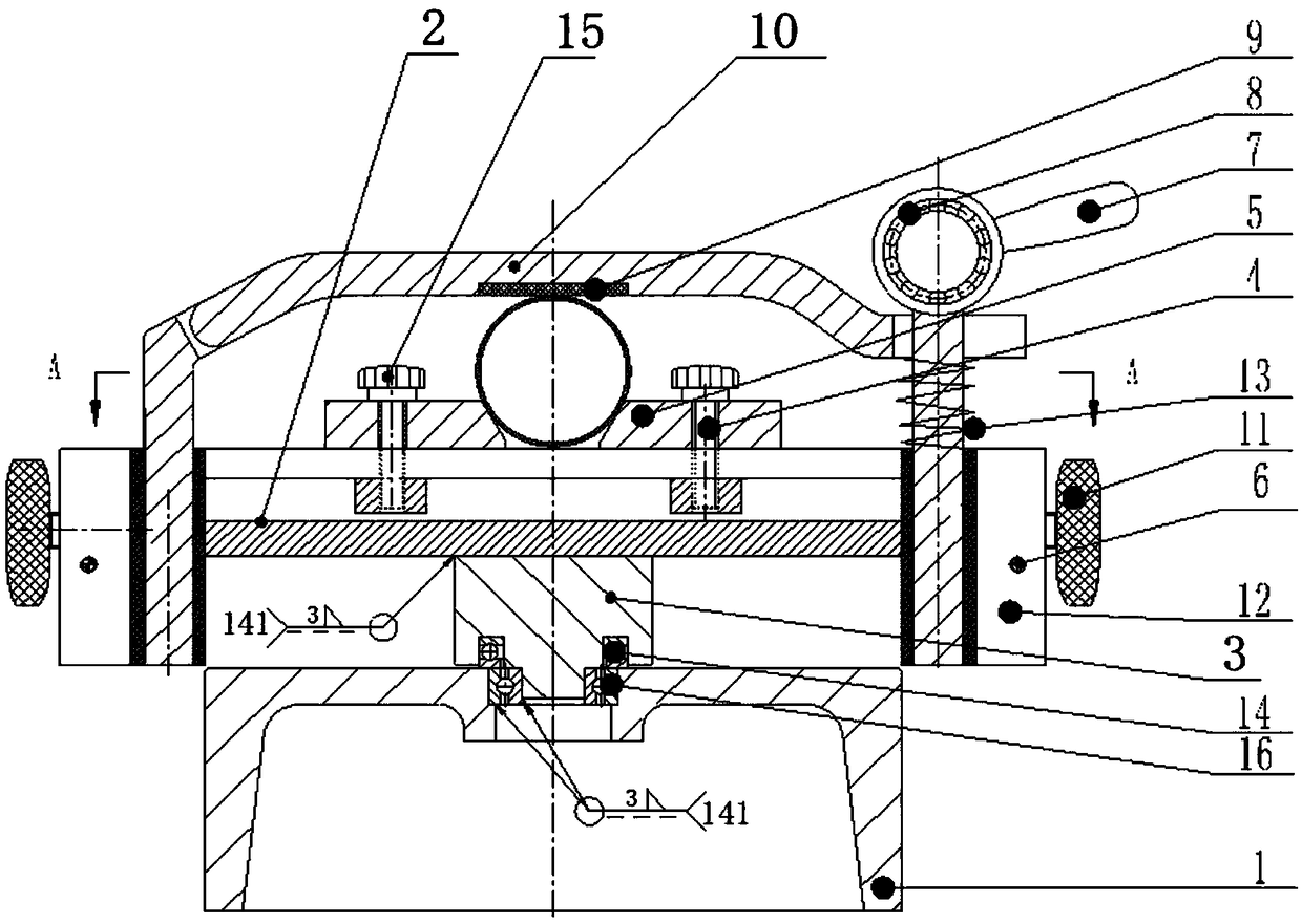
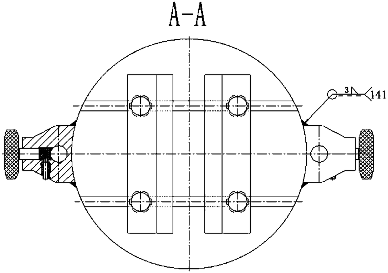
[0029] A rapid assembly positioning welding device for longitudinal welds of thin-walled cylinders with different diameters, which has the advantages of simple product structure, convenient operation, labor-saving and time-saving, and high reliability, such as figure 1 , figure 2 As shown, specifically set to the following structure:

[0030] As an overall concept, the device should include a support seat 1, an installation base 2, a sliding positioning seat assembly, and a compression locking assembly; the support seat 1 is used as a support platform in the device, and is machined from a 45# steel plate of a certain specification. The bottom is a hollow structure to reduce the weight of the parts; the installation base 2 is used as the installation and support platform for each part in the device, and is machined from a 45# steel plate of a certain specification.

[0031] The installation base 2 is fixedly installed on the top of the support base 1 by bolts or welding, and ...

Embodiment 2

[0039] This embodiment is further optimized on the basis of the above-mentioned embodiments, further to better realize the present invention, especially adopt the following configuration structure:

[0040] A locking mounting seat 12 is fixedly connected to both sides of the mounting base 2 by argon arc welding. The locking mounting seat 12 is processed by a certain specification of 45# steel plate. The locking mounting seat 12 is processed with a vertical through pin hole, the locking mounting seat 12 is equipped with a locking bolt 11 and a locking bolt 6 for locking the locking bolt 11, and the locking bolt 11 is processed with textured knurling to facilitate manual operation; the pin of the pressure plate assembly 10 The shaft is movably inserted in the pin hole of a locking mount 12, the pin shaft of the eccentric lock assembly 7 is movably inserted in the pin hole of another locking mount 12, the pin shaft of the pressure plate assembly 10 and the eccentric lock assembly ...


PUM


Abstract

The invention relates to the field of manufacturing of flame tubes of aero-engine combustion chambers, in particular to a rapid assembling and tack welding device for longitudinal welds of thin-wall tubes of different diameters, and aims to solve the problems that in the prior art, the operation is troublesome, both the time and the effort are wasted, the reliability is low, and the processing cost is high due to the usual application of a dozen sets of toolings to the tack welding of a gas film section. In order to solve the problems in the prior art, the rapid assembling and tack welding device for the longitudinal welds of the thin-wall tubes of different diameters is provided. The rapid assembling and tack welding device comprises a supporting seat, a mounting base, two sliding positioning seat assemblies and a compression locking assembly, wherein the mounting base is mounted at the top of the supporting seat; the sliding positioning seat assemblies are slidably arranged on the top surface of the mounting base and sequentially distributed along the guiding directions of guiding slots on the mounting base; and the bottoms of the sliding positioning seat assemblies are in pilotfit with the guiding slots. Compared with the prior art, the rapid assembling and tack welding device can be applied to the rapid assembling and tack welding of the tubes of different diameters withina certain range, and has the advantages that the product structure is simple, the operation is convenient, both the effort and the time are saved, and the reliability is relatively high.

Description

technical field [0001] The invention relates to the field of flame tube manufacturing of aero-engine combustors, in particular, it is a rapid assembly positioning welding device for longitudinal welds of thin-walled tubes with different diameters, and is used for each gas film section tube of a combustor flame tube of an aero-engine Body and other assembly tack welding. Background technique [0002] The flame tube is an important part of the combustion chamber of the aero-engine. It is made of multi-section air film section cylinders through welding, machining and assembly; the air film section of the flame tube is a thin-walled cylinder structure, which is formed by bending and welding sheets Its diameter varies. During welding, it is necessary to position and compress the cylinder through the tooling to ensure the gap and misalignment of the welded joints. [0003] In the prior art, more than a dozen sets of tooling are usually used for the positioning welding of the mul...

Claims


Application Information

Patent Timeline
IPC IPC(8): B23K37/04
CPCB23K37/0443B23K37/0461
Inventor 左治建张晓华
Owner AECC AERO SCI & TECH CO LTD
Learn More