
System for reducing steel water consumption in steelmaking process

A molten steel and steel alloy technology, applied in the direction of manufacturing converters, etc., can solve the problems of high back blowing rate, difficult to reduce iron consumption, and small amount of slag added, so as to achieve the effect of convenient material addition, reduction of molten iron consumption and improvement of strength.

Active Publication Date: 2018-12-18
苏州涵轩信息科技有限公司
View PDF7 Cites 0 Cited by
  • Summary
  • Abstract
  • Description
  • Claims
  • Application Information

AI Technical Summary

Problems solved by technology

However, due to the frequent operation of the converter feeding and the complicated interlocking operation of the feeding system equipment, the labor intensity and experience requirements for the converter feeding operators are relatively high
[0003] Under the production conditions of the existing technology, the reduction of iron consumption and the increase of production capacity have reached the bottleneck period. In order to further reduce the consumption of molten iron, due to the large fluctuations in the conditions of molten iron in the existing production process, especially when the silicon content of the molten iron is less than 0.35%, the temperature is low At 1300°C, there are many problems, such as: 1. It is not conducive to reducing iron consumption. 2. The amount of slag added is small, and it is not easy to remove phosphorus. The post-blowing rate is high, which has a great impact on the furnace condition.
In addition, the reduction of iron consumption in steel plants depends on the conditions of molten iron, and it is difficult to reduce iron consumption. In the current situation where steel scrap is not baked, there is limited space for further reducing iron consumption, especially in the case of low silicon content in molten iron. The above problems are Problems that need to be solved in this field

Method used


Image

  • System for reducing steel water consumption in steelmaking process
  • System for reducing steel water consumption in steelmaking process
  • System for reducing steel water consumption in steelmaking process

Examples


Embodiment Construction

[0021] The present invention will be further described below in conjunction with the accompanying drawings and specific embodiments, so that those skilled in the art can better understand the present invention and implement it, but the examples given are not intended to limit the present invention.

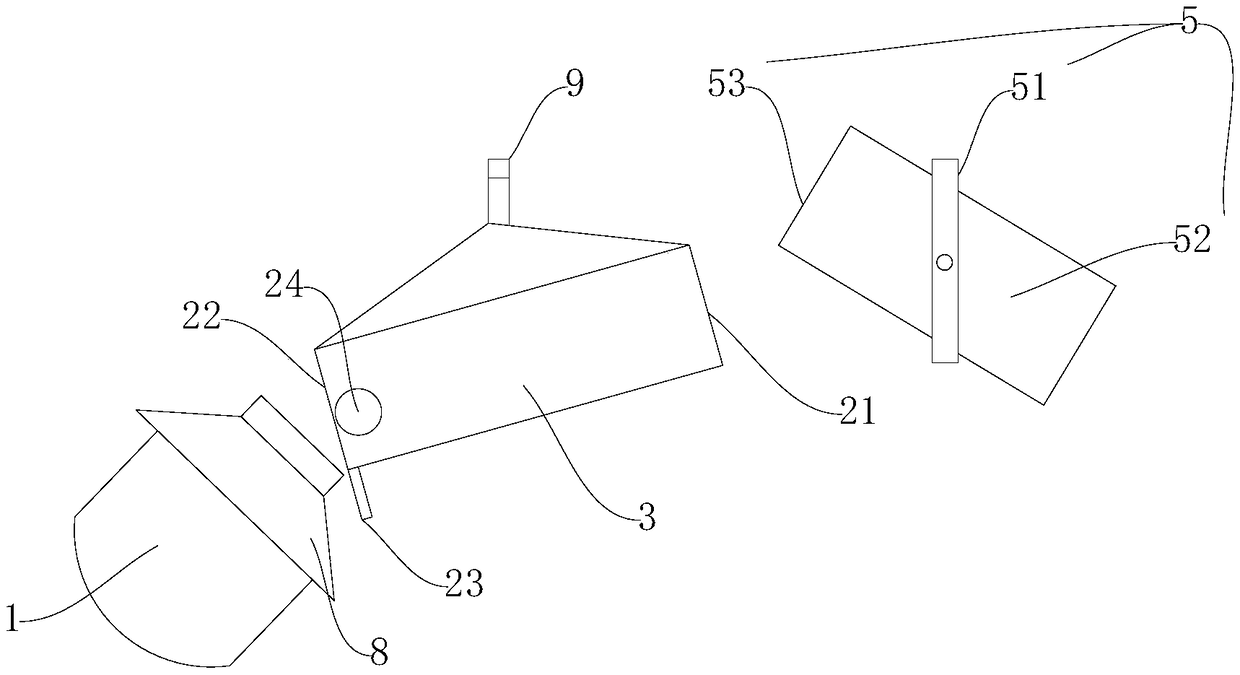
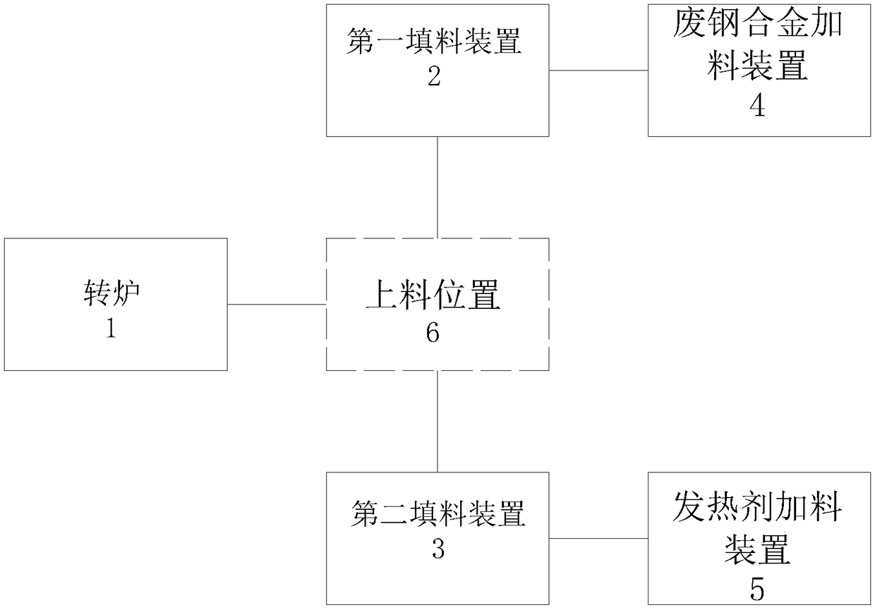
[0022] A system for reducing consumption of molten steel in a steelmaking process, comprising a converter 1 , a first packing device 2 , a second packing device 3 , a scrap steel alloy feeding device 4 and a heating agent feeding device 5 .

[0023] The first filling device 2 and the second filling device 3 fill the converter 1 at the charging position 6, and the first filling device 2 can move back and forth between the first charging position and the charging position 6, so The second filling device 3 can move back and forth between the second charging position and the loading position 6. Specifically, the second filling device 3 includes a second material inlet 31 and a second m...


PUM


Abstract

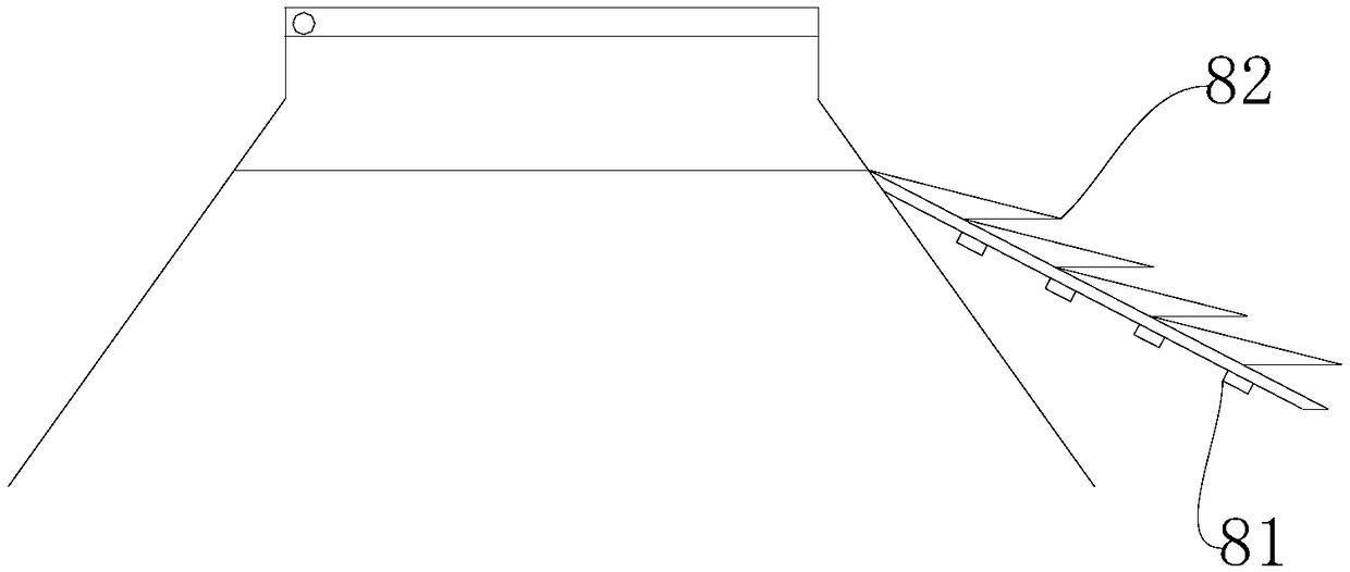
The invention discloses a system for reducing steel water consumption in a steelmaking process. The system comprises a converter, a first packing device, a second packing device, a scrap steel alloy feeding device and a heating agent feeding device; the first packing device can move back and forth between a first charging position and a feeding position; the second packing device can move back andforth between a second charging position and the feeding position; the scrap steel alloy feeding device is used for feeding the first packing device; the first packing device and the second packing device are each provided with a weight sensor; the heating agent feeding device is loaded with a heating agent; a slag blocking plate is further arranged on the converter; a plurality of reinforcing ribs are arranged on the inner side of the slag blocking plate; and a plurality of protruding steps are further arranged on the surface of the slag blocking plate. By arranging the heating agent feedingdevice, molten iron consumption can be effectively reduced by adding the heating agent into the converter, in addition, the first packing device and the second packing device are arranged, the weightsensor are arranged, and thus the proportion of scrap steel to the heating agent can be accurately controlled.

Description

technical field [0001] The invention relates to the field of steelmaking equipment, in particular to a system for reducing consumption of molten steel in the steelmaking process. Background technique [0002] For a long time, converter smelting has been one of the most commonly used smelting methods for non-ferrous metal smelting. Among them, in the process of converter blowing, it is necessary to add cold material and flux, and the amount of added cold material and flux directly affects the time of converter blowing and the grade of the final copper matte. However, since the converter charging requires frequent operations, and the interlocking operation of the feeding system equipment is complicated, the labor intensity and experience requirements for the converter charging operators are relatively high. [0003] Under the production conditions of the existing technology, the reduction of iron consumption and the increase of production capacity have reached the bottleneck ...

Claims


Application Information

Patent Timeline
Patent Type & Authority Applications(China)
IPC IPC(8): C21C5/46C21C7/00
CPCC21C5/466C21C7/005
Inventor 陈士波
Owner 苏州涵轩信息科技有限公司
Learn More