

Warping bobbin creel for fine metal wires
A creel and wire technology, which is applied in the field of spinning machinery components, can solve problems such as kinks or end breaks, and metal wire coating wear, and achieve the effects of reducing wire kinks, uniform tension, and improving warping quality
- Summary
- Abstract
- Description
- Claims
- Application Information
AI Technical Summary
Problems solved by technology
Method used
Image

Examples
Embodiment 1
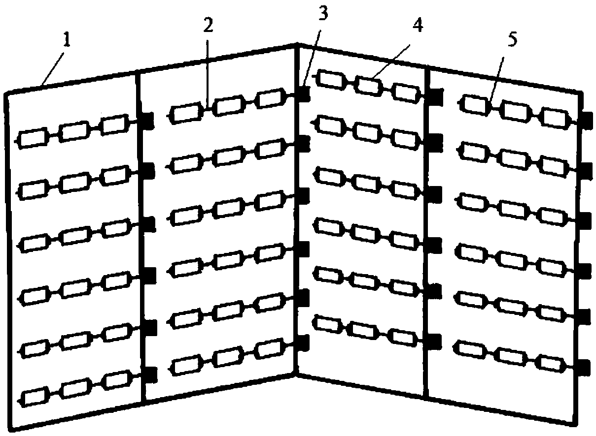
[0023] This embodiment provides a warping creel for fine metal wires, including a creel 1 and a bobbin inserting rod 2, see figure 1 , the warping creel also includes: an electromagnetic brake 3; each bobbin insertion rod 2 on the warping creel corresponds to an electromagnetic brake 3, and the electromagnetic brake 3 is used to drive its corresponding bobbin The plunger 2 is self-rotating.
[0024] During the warping process, the rotation of the yarn bobbin rod 2 is controlled by the electromagnetic brake 3, and then the yarn bobbin 4 on the yarn bobbin rod 2 is driven to rotate, so that the yarn bobbin 4 realizes self-rotation and unwinding, and the metal wire on it is cut The unwinding is carried out in a combination of directional unwinding and self-rotating unwinding, thereby avoiding the problems of kinks or end breaks and wire coating wear caused by the torque of the fine metal wires during the process of unwinding from the creel to the warping head.
Embodiment 2
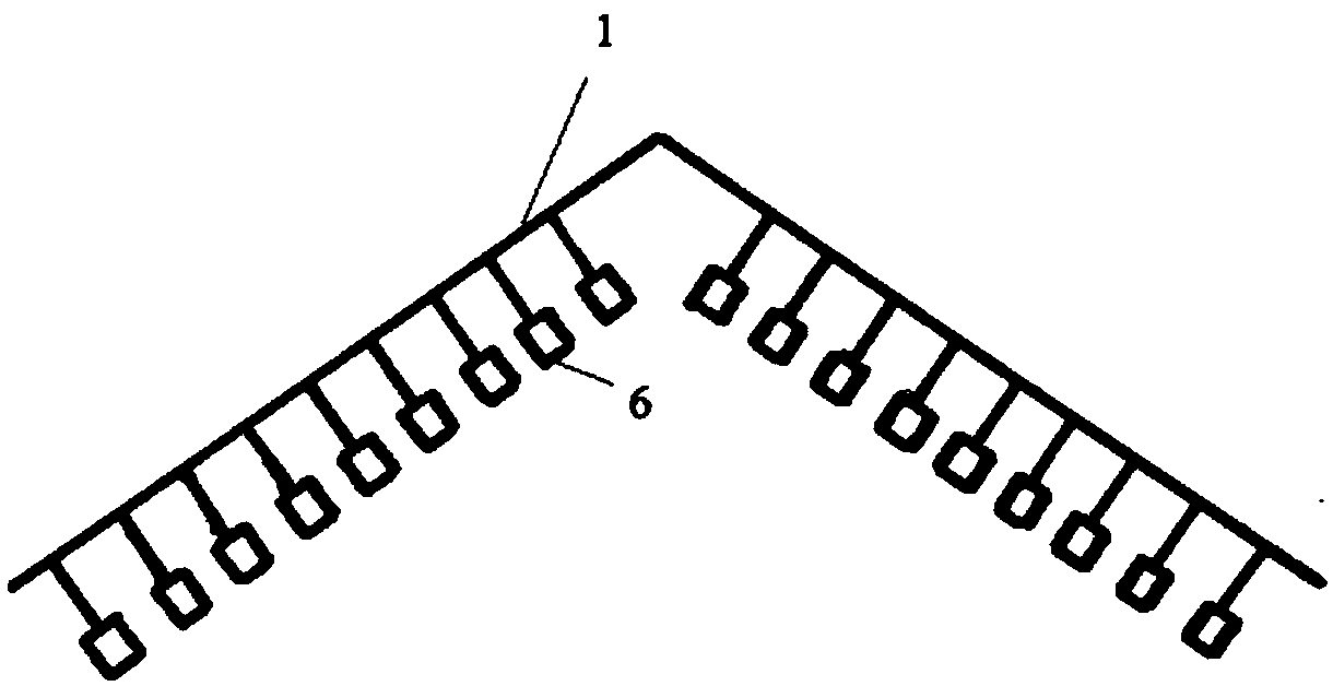
[0026] This embodiment provides a warping creel for fine metal wires, including a creel 1 and a bobbin inserting rod 2, see figure 1 and figure 2 , the micro-wire warping creel provided by the embodiment of the present invention also includes an electromagnetic brake 3, a bobbin 4, a rubber ring 5 and a tension controller 6;
[0027] Among them, the creel 1 is a V-shaped creel, and the bobbin insertion rods 2 are arranged in dislocation on both sides of the V-shaped creel 1, and each bobbin insertion rod 2 corresponds to an electromagnetic brake 3, and the electromagnetic brakes 3 are connected to the PLC control On the machine, the PLC controls the connection with the servo motor. During warping, the yarn bobbin 4 is driven by the servo motor to rotate and unwind. Further, the yarn bobbin 4 is fixed on the yarn bobbin inserting rod 2 with the assistance of the rubber ring 5. Each There is a tension controller 6 in front of the yarn bobbin 4, and the tension controller 6 is ...
PUM
 Abstract
Description
Claims
Application Information