Grouting pipe with improved grouting effect and grouting process

A technology of grouting effect and grouting pipe, which is applied in the direction of shaft lining, tunnel lining, underground chamber, etc., can solve the problems of easy collapse, broken rock mass, unknown grout where to go, etc., to achieve firm installation, avoid grout loss, and ensure The effect of the grouting effect

Active Publication Date: 2018-12-18
江苏华设远州交通科技有限公司 +1
View PDF7 Cites 6 Cited by
  • Summary
  • Abstract
  • Description
  • Claims
  • Application Information

AI Technical Summary

Problems solved by technology

[0002] The tunnel entry section and the tunnel body are located in the weak surrounding rock zone, and the rock mass is broken and easy to collapse. Generally, grouting measures are taken to improve the surrounding rock. However, in many cases, the existing technology cannot achieve the expected effect. Mortar is easily taken away by water in unfavorable geology such as water strata, and the processing effect is not ideal, which is a difficult problem

Method used


Image

  • Grouting pipe with improved grouting effect and grouting process
  • Grouting pipe with improved grouting effect and grouting process
  • Grouting pipe with improved grouting effect and grouting process

Examples


Embodiment 1

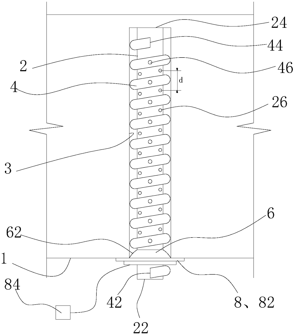
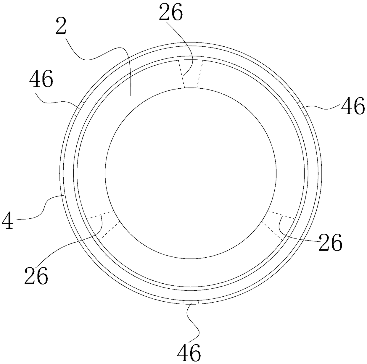
[0052] like Figure 1-4 As shown, a grouting pipe for improving the grouting effect includes a hollow tubular body 2, one end is a grouting port 22, and the other end is a grouting port 24. In addition, the side of the body 2 is also provided with a number of holes capable of releasing the grout. The first slurry outlet 26. In addition, the grouting pipe also includes a branch pipe 4 that spirally surrounds the outside of the body 2. One end of the branch pipe 4 near the grout inlet 22 of the body 2 is also provided with a branch pipe grout inlet 42, and the other end is a branch pipe outlet 44. A plurality of second slurry outlets 46 capable of releasing slurry to the outside are provided on the pipe body.

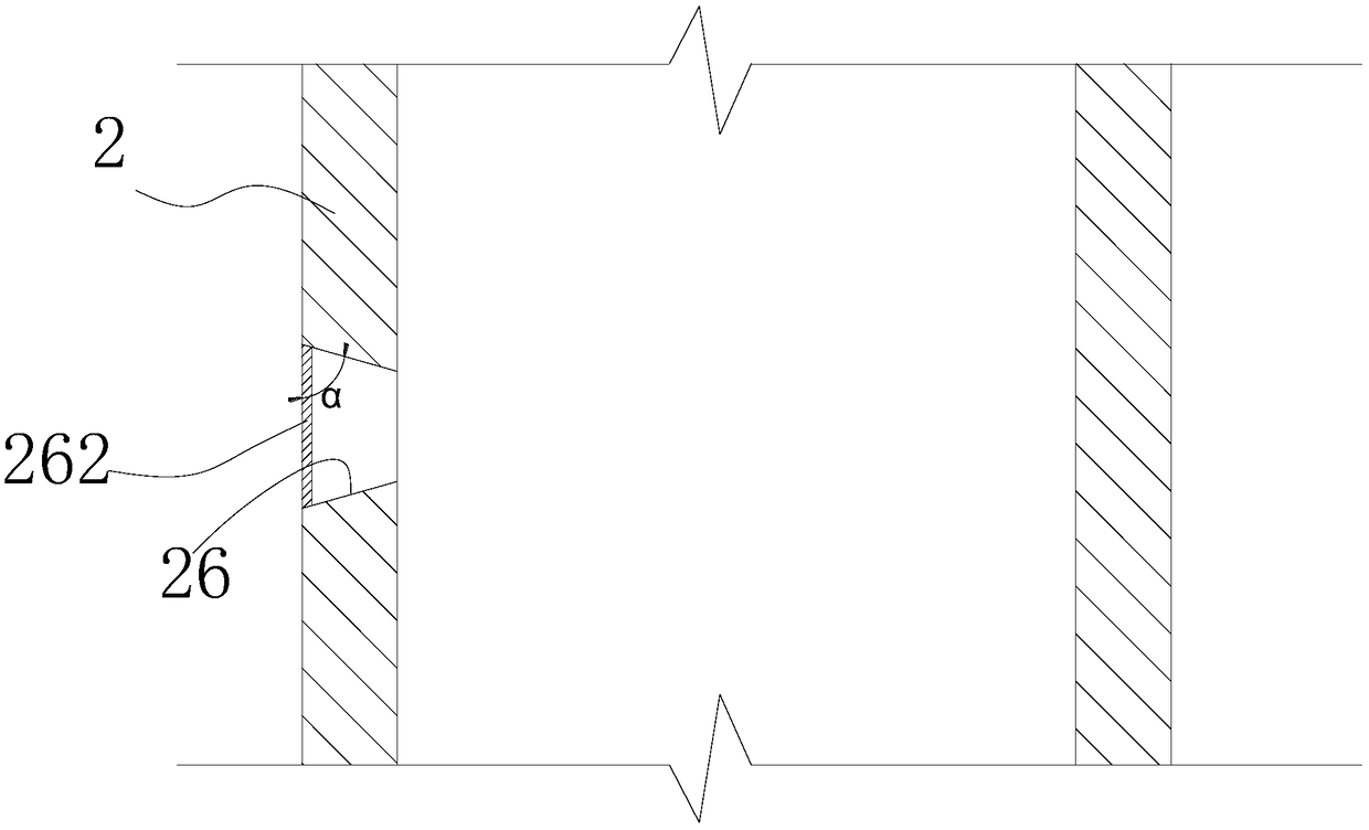
[0053] Specifically, the first grout outlet 26 is provided with a layer of thin wall 262 that can be broken through by the grouting pressure, and the second grout outlet 46 is also provided with a layer of thin wall 462 that can be broken through by the grouting pressure...

Embodiment 2

[0062] like Figure 2-7 As shown, a grouting pipe for improving the grouting effect is different from Embodiment 1 in that: the grouting pipe body 2 includes a plurality of tubular body units 28 connected end-to-end in the axial direction, and two adjacent body units 28 are detachably inserted Connected together, there is an overlapping portion 282 , and the first pulp outlet 26 is opened on the overlapping portion 282 . A tubular connecting piece 29 is also embedded in the first pulp outlet 26 on the overlapping portion 282 , and the two ends of the tubular connecting piece 29 have flanges respectively so as to connect the two body units 28 together. Specifically, the flanging at one end of the tubular connector 29 is a fixed annular flanging 292, and the other end is a separate three to four independent flanging 294, and the flanging 294 is a foldable metal or plastic sheet, which adopts the common When in use, the flange 294 is opened to be parallel to the axial direction ...

Embodiment 3

[0066] A kind of tunnel grouting process of the present invention, comprises the steps:

[0067] (1) Preparatory work, processing the grouting hole 3 at the target position of the tunnel;

[0068] (2) insert the grouting pipe of embodiment 1 in the grouting hole 3;

[0069] (3) Push the grout stopper 6 into the grouting hole 3, check the seal, and fix the grouting pipe on the operation target through the vacuum adsorption device 8;

[0070] (4) Inject mortar through the body 2 of the grouting pipe, and inject quick-setting agent through the branch pipe 4. Specifically, the grouting should be performed slowly first, so that the inner end of the grouting pipe is filled first, and then the entire cavity of the grouting pipe is gradually filled.


PUM


Abstract

The invention discloses a grouting pipe with an improved grouting effect. The grouting pipe comprises a hollow tubular body, a plurality of first spouting ports disposed on the side portion of the body and capable of spouting slurry outwards, and a branch pipe spirally surrounding the outer side of the body and provided with a plurality of second spouting ports capable of spouting the slurry outwards. Therefore, the grouting pipe has two passages including the body and the branch pipe through which mortar and a cement accelerator can be poured simultaneously and respectively. The combination of the body and the branch pipe has a better rock formation reinforcement effect, especially for water-rich rock formations. A tunnel grouting process, by using the grouting pipe of the present invention, can easily and simultaneously pour the mortar and the cement accelerator, is simple in process and has a better rock formation reinforcement effect.

Description

technical field [0001] The invention relates to a grouting pipe and a grouting process for improving the grouting effect. Background technique [0002] The tunnel entry section and the tunnel body are located in the weak surrounding rock zone, and the rock mass is broken and easy to collapse. Generally, grouting measures are taken to improve the surrounding rock. However, in many cases, the existing technology cannot achieve the expected effect. Mortar is easily taken away by water in unfavorable geology such as water strata, and the processing effect is not ideal, which is a difficult problem. Contents of the invention [0003] The invention overcomes the shortcomings of the prior art and provides a grouting pipe which can effectively improve the grouting effect and a grouting process using the grouting pipe. [0004] In order to achieve the above object, the technical scheme adopted in the present invention is: [0005] A grouting pipe for improving the grouting effect...

Claims


Application Information

Patent Timeline
IPC IPC(8): E21D9/00E21D11/10
CPCE21D9/001E21D11/10
Inventor 葛志华唐冲刘铭钰张鸿基
Owner 江苏华设远州交通科技有限公司
Why Eureka
Try Eureka