High-pressure composite container with sealed structure

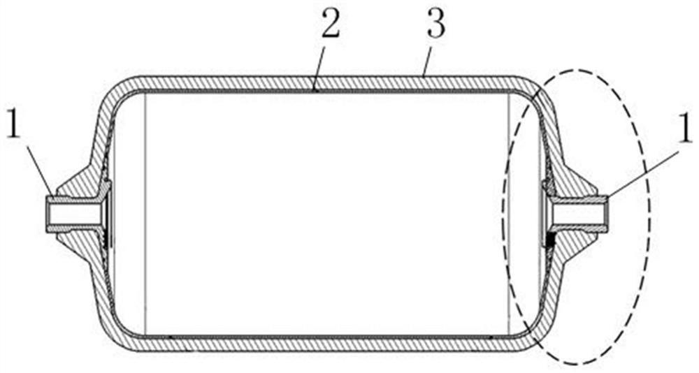
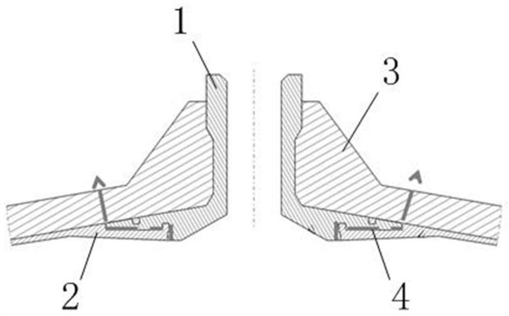
A composite container and sealing structure technology, applied in the field of composite containers, can solve the leakage of the gap between the metal end 1 and the plastic inner tank 2, the reduction of the bonding strength of the metal end 1 and the reinforcement layer 3, and the increase of the risk of compressed gas escape and other problems to achieve the effect of extending the mating interface, enhancing the sealing, preventing leakage or penetration

Active Publication Date: 2021-02-02
YAPP AUTOMOTIVE PARTS
View PDF6 Cites 0 Cited by
  • Summary
  • Abstract
  • Description
  • Claims
  • Application Information

AI Technical Summary

Problems solved by technology

figure 2 for figure 1 The sealing structure in the high-pressure plastic liner composite container shown, such as figure 1 and figure 2 As shown, the large-surface contact between the metal end 1 and the plastic liner 2 is technically infeasible, and even if it is feasible, the cost is high; this sealing structure does not consider the limit on the axis of the metal end 1 and the plastic liner 2 ; This structure does not take into account the constant change of the internal pressure of the plastic liner 2 during winding, which will cause a gap in the connection between the metal end 1 and the plastic liner 2 to cause leakage, such as figure 2 Leakage path 4 shown by the arrow in the middle; this structure does not consider the limit when the bottle mouth is subjected to installation torque, and the bonding strength between the metal end 1 and the reinforcement layer 3 is reduced after installation; the escape path P of the compressed gas in this structure is relatively short , will increase the risk of compressed gas escape, especially small molecule gases CNG, hydrogen, helium, etc.

Method used


Image

  • High-pressure composite container with sealed structure
  • High-pressure composite container with sealed structure
  • High-pressure composite container with sealed structure

Examples


Embodiment Construction

[0046] Embodiments of the present invention are described in detail below, examples of which are shown in the drawings, wherein the same or similar reference numerals designate the same or similar elements or elements having the same or similar functions throughout. The embodiments described below by referring to the figures are exemplary only for explaining the present invention and should not be construed as limiting the present invention.

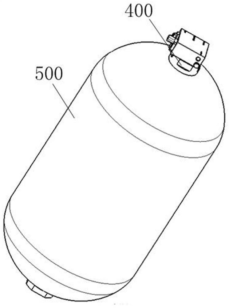
[0047] Please also refer to Figure 3 to Figure 7 , the embodiment of the present invention provides a high-pressure composite container, which includes a shell 300, a support liner 200, a terminal 100, a bottle mouth valve 400, and a reinforcement layer 500; wherein, the shell 300 is provided with a bottle mouth 310 to support The inner liner 200 is clamped on the outer ring of the bottle mouth 310, and the terminal 100 is provided with a mounting groove 122, and the terminal 100 is clamped on the outer ring of the supporting inner line...


PUM


Abstract

The invention discloses a high-pressure composite container with a sealed structure, which includes a shell, a supporting inner liner, a terminal, a bottle mouth valve and a reinforcement layer; On the outer ring of the mouth, the bottle mouth valve is fixedly installed in the end, and the reinforcement layer is wrapped on the shell. The sealing structure for the high-pressure composite container provided by the present invention can wrap the supporting lining and the bottle mouth in the installation groove through the cooperation of the end, the supporting lining and the bottle mouth, thereby enhancing the sealing performance of the structure and extending the The matching interface between the end and the shell is improved, that is, the leakage path of the gas is extended, which effectively prevents the leakage or penetration of the high-pressure gas in the container, and ensures the sealing effect of the container.

Description

technical field [0001] The invention relates to a composite container, in particular to a high-pressure composite container with a sealing structure. Background technique [0002] Most taxis are converted to compressed natural gas (CNG) to replace fuel. Generally, the working pressure of CNG high-pressure cylinders is 20MPa; some vehicle manufacturers have promoted vehicles that use CNG or CNG mixed with fuel, such as Audi and GM. Vehicles using hydrogen-dielectric batteries are also a current hot spot. The working pressure of hydrogen storage high-pressure gas cylinders is generally 35MPa and 70MPa, and the 70MPa type IV bottle (high-pressure plastic liner composite container) is a current research and development hotspot. In addition to vehicle use, high-pressure gas cylinders are also fully used in other fields. For example, some liquefied petroleum gas in Europe uses plastic liner composite containers (working pressure 2MPa). A large number of high-pressure containers a...

Claims


Application Information

Patent Timeline
Patent Type & Authority Patents(China)
IPC IPC(8): F17C13/06F17C13/00
CPCF17C13/002F17C13/06F17C2201/0109F17C2201/032F17C2201/056F17C2203/0604F17C2205/0305F17C2205/0311F17C2221/033F17C2223/0123F17C2270/0178
Inventor 姜林刘亮吕昊翁益明苏卫东王安玉
Owner YAPP AUTOMOTIVE PARTS
Why Eureka
Try Eureka