A low-profile CTS plate array antenna

一种阵列天线、低剖面的技术,应用在天线、隙缝天线、天线阵列等方向,能够解决偏置抛物反射面加工要求高、装配要求过程复杂、装配要求高等问题,达到结构设计紧凑、实现剖面的设计、降低加工难度的效果

Inactive Publication Date: 2018-12-18
NINGBO UNIV
View PDF9 Cites 9 Cited by
  • Summary
  • Abstract
  • Description
  • Claims
  • Application Information

AI Technical Summary

Problems solved by technology

[0004] However, the existing CTS flat-panel array antennas have the following problems: 1. The offset parabolic reflector of the flat-panel reflector requires a large space and a large size; 2. The processing requirements of the offset parabolic reflector are relatively high, and the , the focus of the offset parabolic reflector and the phase center of the H-plane fan-shaped horn antenna need to be strictly aligned, and the assembly requirements are high; 3. The waveguide power divider is formed by layering at least four waveguide power layers, and the size is large, and each Each waveguide power layer needs to be processed separately and then assembled. The assembly process is complicated and the assembly requirements are high.

Method used


Image

  • A low-profile CTS plate array antenna
  • A low-profile CTS plate array antenna
  • A low-profile CTS plate array antenna

Examples


Embodiment

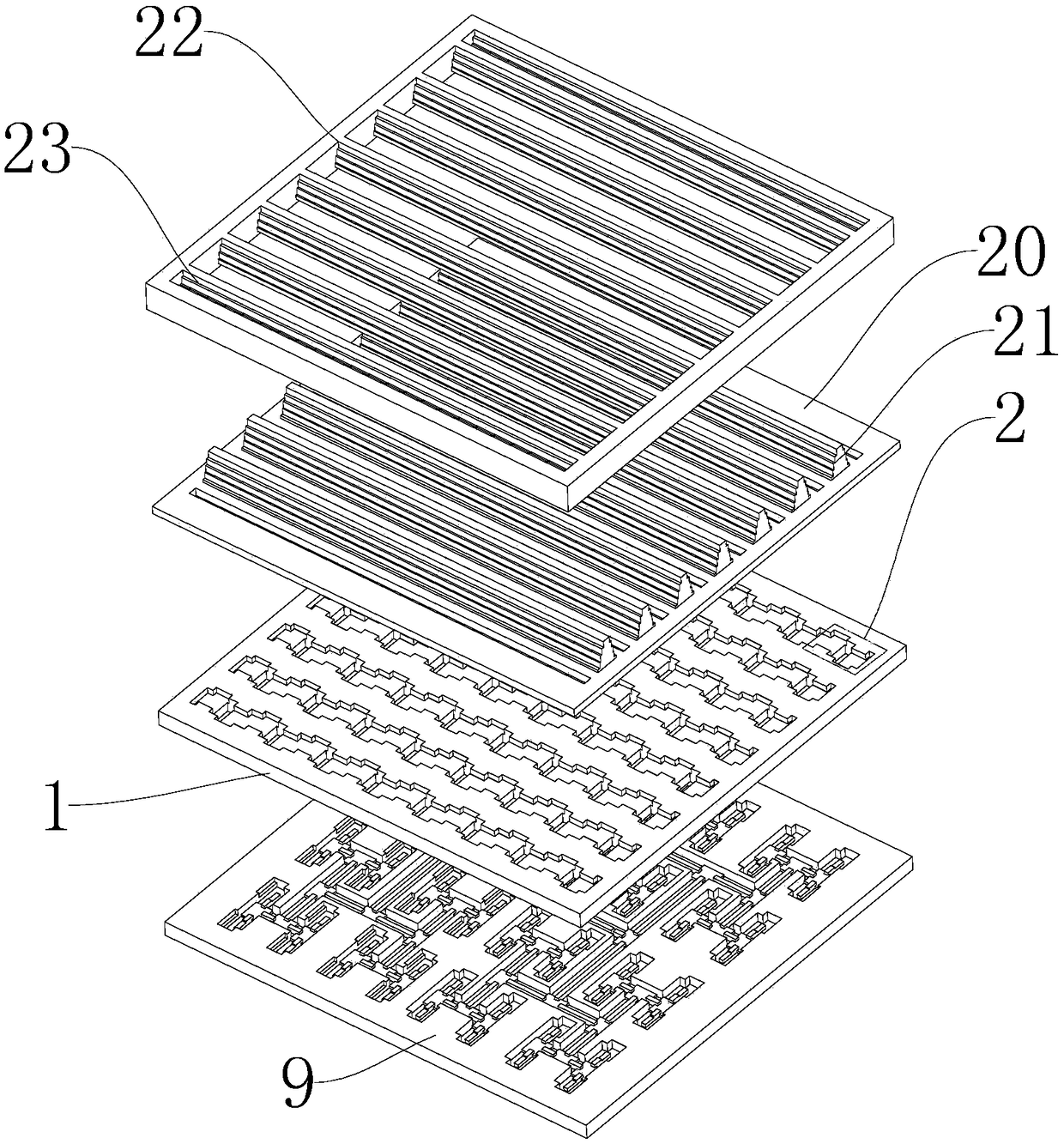
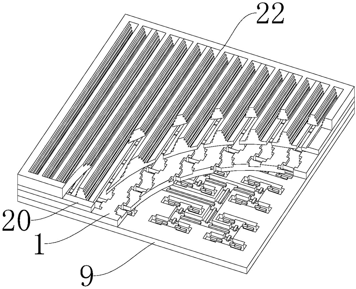
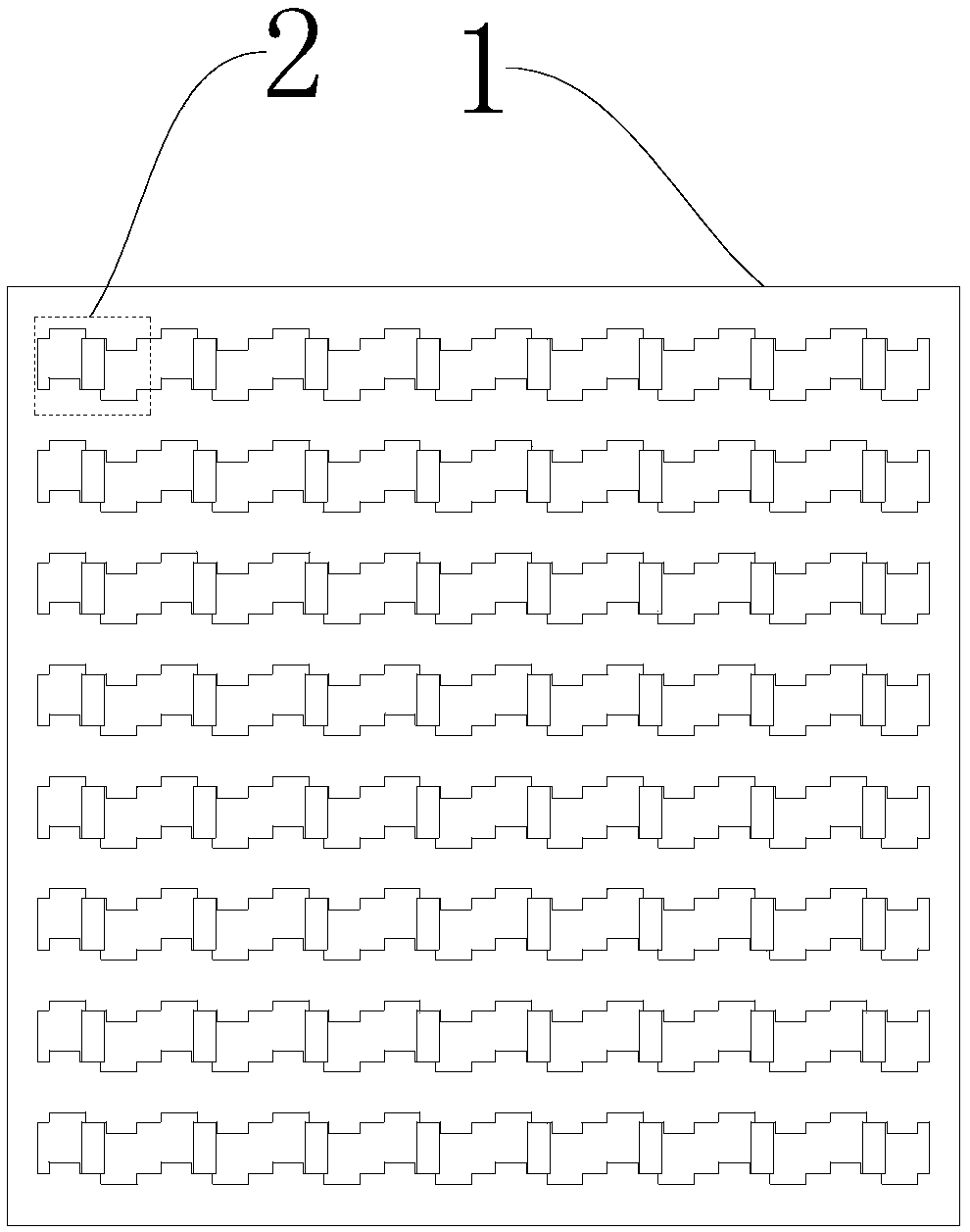
[0020] Embodiment: As shown in the figure, a low-profile CTS planar array antenna includes a radiation layer, a mode conversion layer, and a feed network layer arranged in sequence from top to bottom. The mode conversion layer includes a first metal plate 1 and a second A mode conversion cavity array on the upper surface of a metal plate 1, the mode conversion cavity array includes 2 2n mode conversion cavities 2, 2 2n mode conversion cavity 2 in accordance with 2 n row x 2 n Arranged in columns, n is an integer greater than or equal to 1, and 2 in the same row n The three mode conversion cavities 2 are connected end to end in sequence; the mode conversion cavity 2 includes a first rectangular cavity 3, a second rectangular cavity 4, a third rectangular cavity 5, a fourth rectangular cavity 6 and a fifth rectangular cavity 7 connected in sequence from left to right , the row direction of the long edge mode conversion cavity array of the first rectangular cavity 3, the secon...


PUM


Abstract

The invention discloses a low-profile CTS plate array antenna, which comprises a radiating layer, a mode conversion layer and a feed network layer arranged in order from the top to the bottom, the mode conversion layer includes a first metal plate and a mode conversion cavity array arranged on an upper surface of the first metal plate, the mode conversion cavity array includes 22n mode conversioncavities, the 22n mode conversion cavities are arranged in 2n rows by 2n columns, n is an integer greater than or equal to 1, and the mode conversion cavities comprise a first rectangular cavity, a second rectangular cavity, a third rectangular cavity, a fourth rectangular cavity and a fifth rectangular cavity connected in order from left to right, and 2n mode conversion cavities located in the same row are connected in order from end to end; and the antenna provided by the invention has the beneficial effects of wide frequency band, high gain and high efficiency, small size and simple processing and assembly process.

Description

technical field [0001] The invention relates to a CTS panel array antenna, in particular to a low profile CTS panel array antenna. Background technique [0002] In recent years, CTS panel array antennas have attracted more and more attention due to their characteristics of low VSWR, high gain, high efficiency, low cost and insensitivity to manufacturing precision. The CTS planar array antenna is formed by opening a tangential slot on the parallel plate waveguide. Any longitudinal current component generated by the parallel plate waveguide excited by the plane wave will be cut off by the transverse slot, and a longitudinal displacement current will be generated at the junction of the tangential slot and the parallel plate waveguide. , at this time, the energy transmitted in the parallel plate waveguide can be coupled through the tangential joints and radiate electromagnetic waves outward. [0003] The existing CTS planar array antenna usually includes a planar reflector, a w...

Claims


Application Information

Patent Timeline
Patent Type & Authority Applications(China)
IPC IPC(8): H01Q1/38H01Q1/50H01Q21/00H01Q23/00H01P1/16H01P5/12
CPCH01P1/16H01P5/12H01Q1/38H01Q1/50H01Q21/0006H01Q23/00H01P1/209H01Q13/02H01Q21/064H01Q13/18
Inventor 尤清春黄季甫秦丽婷尤阳
Owner NINGBO UNIV
Why Eureka
Try Eureka